30
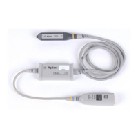
1159A 1GHz Active Differential Probe
Calibration Testing Procedures
13 Calculate CMRR.
14 Record CMRR in the “CMRR at 100 MHz” section of the Calibration Test
Record on page 36.
Note CMRR must 25dB or greater.
Test CMRR at 500 MHz Use setup files 1159CAL4a and 1159CAL4b in this
test.
1
Set the signal generator as shown in the following table.
2 Disconnect the 1159A probe from the CH1 and connect it to CH2 to
maintain a constant temperature.
3 Load setup file 1159CAL4a.
4 Connect the signal generator to CH1 on the oscilloscope.
5 Measure the amplitude of the signal generator output.
Record V1:_____________
6
Remove the signal generator from CH1.
7 Remove the 1159A probe from CH2 and connect it to CH1.
8 Select Auto Zero under the probe menu.
Do not connect the probe tip to the calibration fixture during Auto Zeroing.
9
Connect the signal generator to BNC C of the calibration fixture.
10 Load setup file 1159CAL4b.
11 Connect the 1159A probe to D of the calibration fixture.
12 Measure the maximum value of CH1.
Record V2:_____________
13
Calculate CMRR.
14 Record CMRR in the “CMRR at 500 MHz” section of the Calibration Test
Record on page 36.
Note CMRR must 19dB or greater.
CMRR in dB 20
V2 amplitude
V1 amplitude
--------------------------------
log=
Setting Value
Output Level 5 dBm
Frequency 500 MHz
CMRR in dB 20
V2 amplitude
V1 amplitude
--------------------------------
log=
Artisan Technology Group - Quality Instrumentation ... Guaranteed | (888) 88-SOURCE | www.artisantg.com

 Loading...