40 Installation
GPIB Address
The GPIB address of the Electronic Load is factory set to address 5. The GPIB address can only be set using the front panel
and ENTRY keys. Chapter 4 explains how to change the GPIB address.
Rear Panel Connectors and Switches
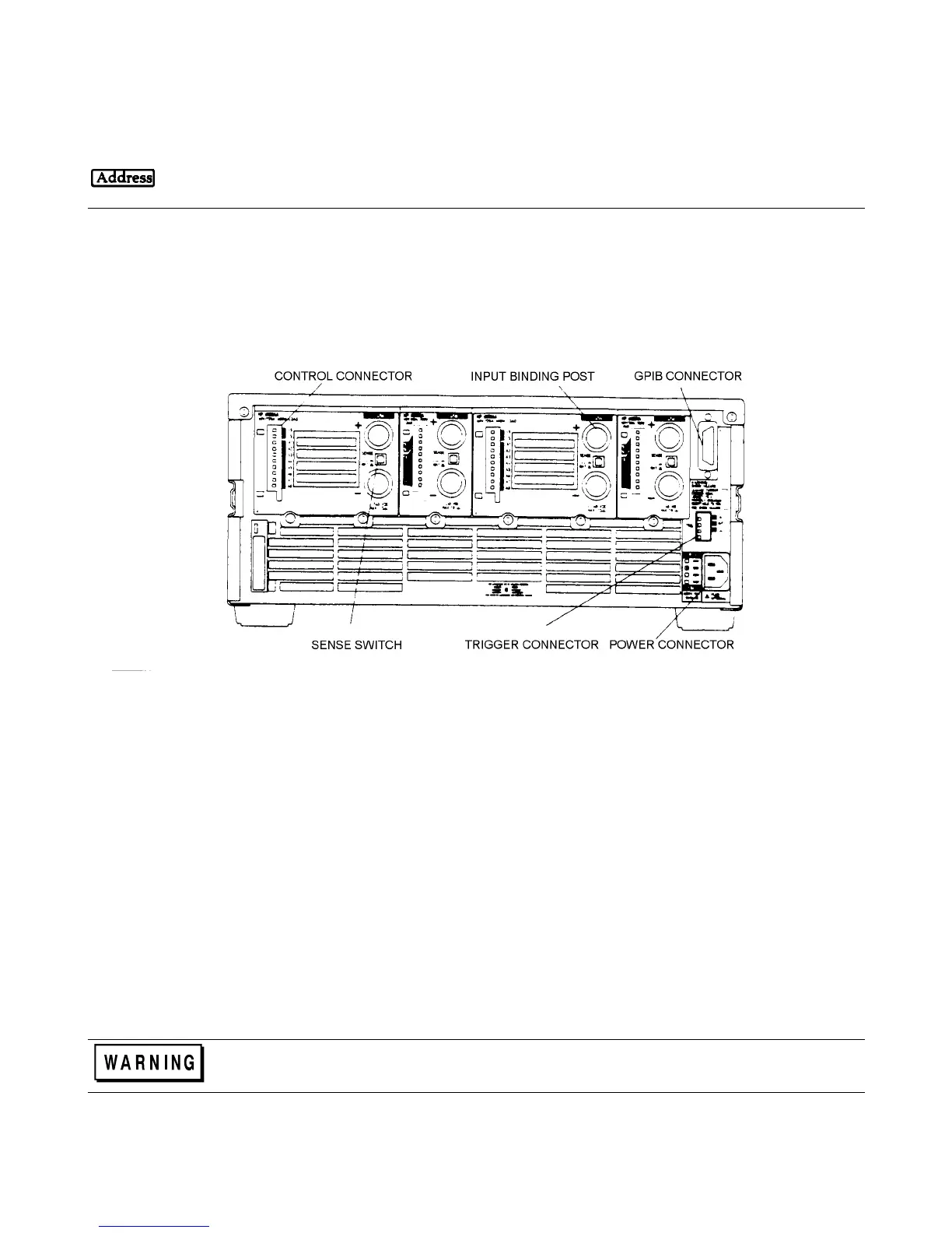
Figure 3-8 shows the rear panel of the Agilent 6050A Electronic Load. The input binding posts, control connectors, and
trigger connector are used for application connections.
Figure 3-8. Rear Panel
Input Binding Posts
Two screw-down binding posts (+ and -) are provided on each module for connecting the input wires to the Electronic Load
(see Figure 3-9). Connections are made as follows:
1. Strip back the wire insulation as indicated:
Wire Size Strip back:
AWG 4 6 mm (0.65 in.)
AWG 6 or 8 13 mm (0.5 in.)
AWG 10 or smaller 10 mm (0.4 in.)
AWG 4 is the maximum wire size. Stranded copper wire, size AWG 6 or 8, is the recommended wire. If you are
connecting more than one wire on each post, twist the wires to ensure a good contact when the adjustment knob is
tightened.
2. Insert the wire into the binding post.
SHOCK HAZARD To prevent accidental contact with hazardous voltages, do not extend the wire
beyond the contact area inside the binding post.