33
Test Setup for Signature Analysis
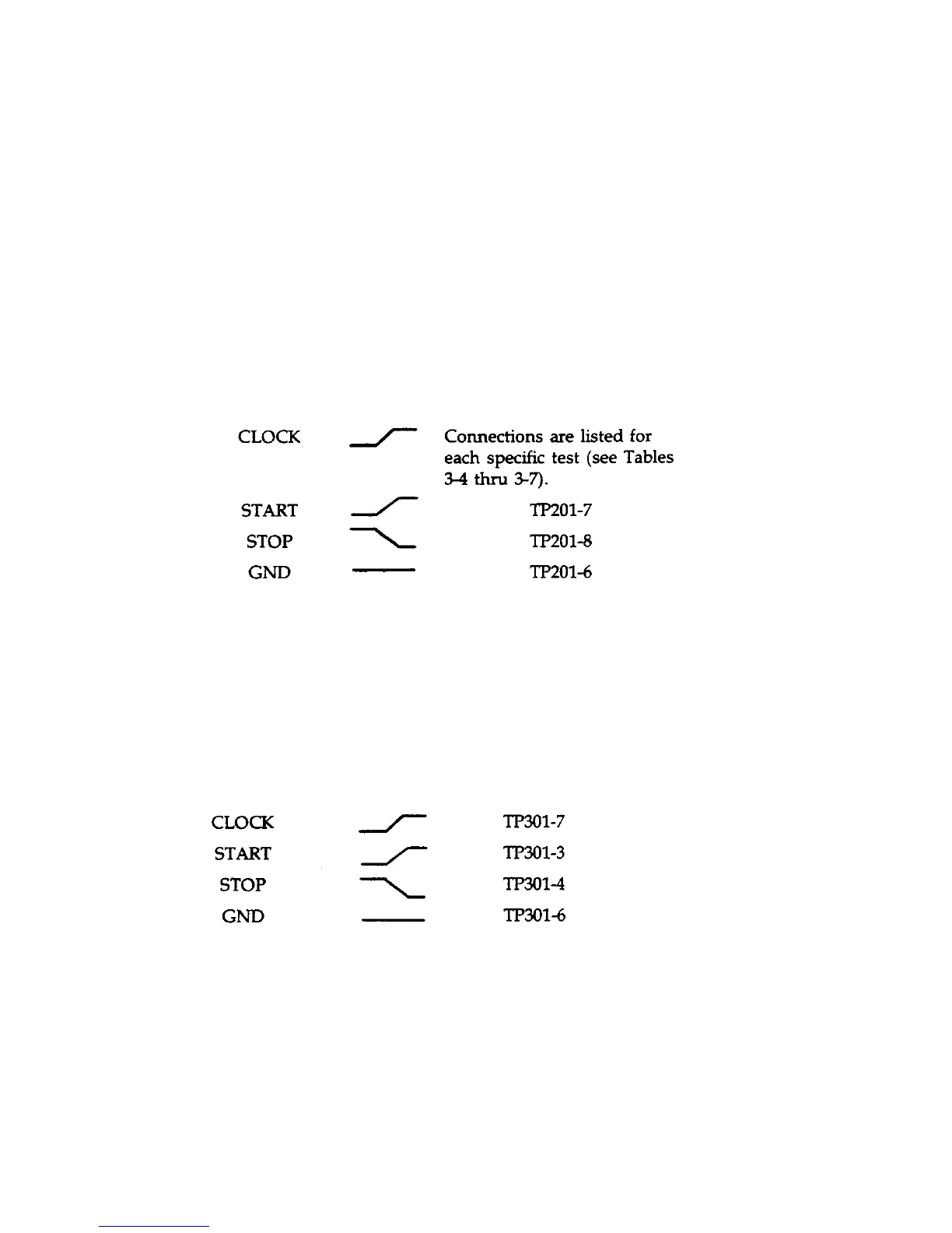
Figure 3-2 illustrates the primary (TP201) and secondary (TP301) test header connections required to perform the S.A.
Tests given in Tables 3-4 through 3-12. The following is a description of the test setup:
a.
Turn off the Electronic Load and gain access to the main circuit board by removing the top cover (see "Disassembly
Procedures"). Make sure that the Electronic Load is turned off before continuing with the test setup.
b. To test the primary interface, use the following test setup.
1.
Connect jumper RTP201 in the S.A. position (SA_MODE) across pins 3 and 4 of the primary test header TP201
(see Figure 3-2).
2.
Set up and connect the signature analyzer's CLOCK, START, STOP, and GND inputs as follows:
Signature Analyzer Edge
Input Setting TP201 Connection
c. To test the secondary interface, use the following test setup.
1.
Connect jumper RTP301 in the S.A. position (SA_EN) across pins 1 and 2 of the primary test header TP301 (see
Figure 3-2).
2.
Set up and connect the signature analyzer's CLOCK, START, STOP, and GND inputs as follows:
Signature Analyzer Edge
Input Setting TP301 Connection
d. Turn on the signature analyzer and use the signature analyzer probe to take signatures at the applicable IC test points
given in the S.A. Test Table.
e. Upon completion of the S.A. tests, return jumpers RTP201 and/or RTP301 to their normal operating positions of
TP201 and TP301 as follows (see Figure 3-2): RPT201 between TP201-7 and TP201-8; RTP301 between TP301-3 and
TP301-4.