56
Overpower Circuit Troubleshooting (Figure 3-10)
This circuit limits the power sinking capability of the load to either one to two minutes or 50 milliseconds, depending on the
temperature of the heatsink assembly.
The circuit monitors the input voltage and current to determine if an overpower condition exists. The circuit consists of
amplifier U12, the four comparators U7, and summing resistor pack R123. Signal levels representing the input voltage and
current are summed with the + 12V reference voltage via resistors to determine if an overpower condition exists. The signal
levels are scaled to allow different combinations of voltage and current to be compared (e.g. high voltage/low current; high
current/low voltage; etc). If the load is operating in overpower and the EPU bit is false, the load may operate in overpower
for up to two minutes until the EPU bit goes true. If EPU is true, the load will only operate in the overpower state for 50
milliseconds before going to power shutdown. The EPU bit (bit 9) setting is dependent on the temperature of the heatsink
assembly.
To check the status of the EPU bit, send the string "STAT:CHAN:COND?".
When the overpower circuit is active, limiting input power capability, the comparator circuit becomes a relaxation oscillator
and its output voltage at test point
will go between -14V and 0V (see waveform on Figure 3-10).
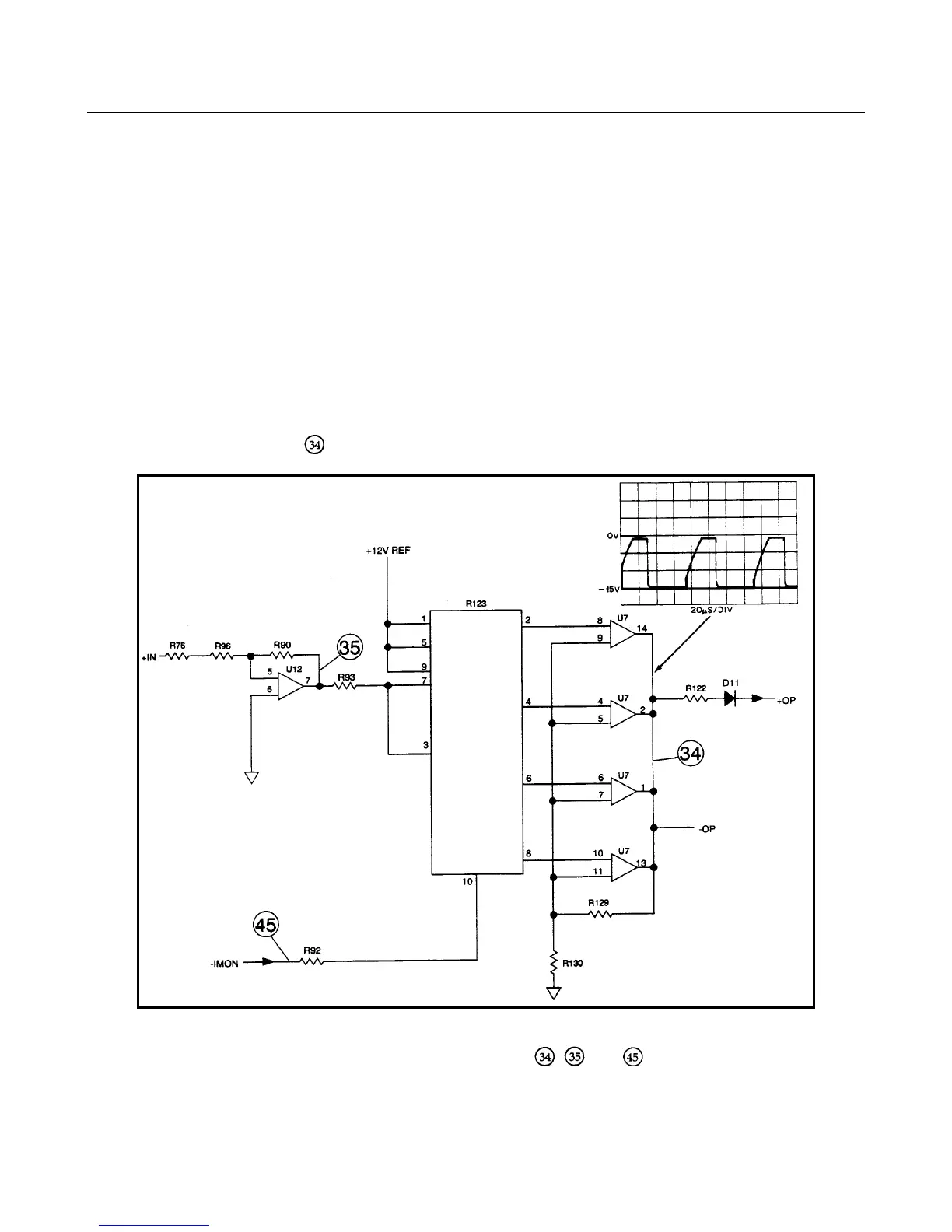
Figure 3-10. Overpower Circuit Troubleshooting
Troubleshooting the power limit circuit consists of checking test points , , and
using the measurement
conditions
and readings specified in table 3-3. Also check the +12V reference, the U7 comparator, resistor pack R123 and temperature
monitor circuit RT551, U327.