B - Verification and Calibration
66
Table B-1. Equipment Required
Equipment Characteristics Recommended Model
Digital Voltmeter
Resolution: 10 nV @ 1 V
Readout: 8.5 digits
Accuracy: >20 ppm
Agilent 3458A
Current Monitor
1
0.01
Ω
,
±
200 ppm, 10 Watts
Guildline 7320/0.01
Ratio Transformer
2
30:1 ratio, 50 ppm, 45 Hz to 1 kHz
Load Resistor
20
Ω
, 10 A, 1800 Watts min.
Impedance Resistor
1
Ω
, 100 Watts min.
GPIB Controller
Full GPIB capabilities HP Series 200/300 or equivalent
1
The 4- terminal current shunt is used to eliminate output current measurement error caused by voltage drops in the
load leads and connections. It has special current-monitoring terminals inside the load connection terminals. Connect
the voltmeter directly to these current-monitoring terminals.
2
A ratio transformer is required only when verifying output voltage readback to MIL-STD-45662A 4:1 test
equipment ratio requirements.
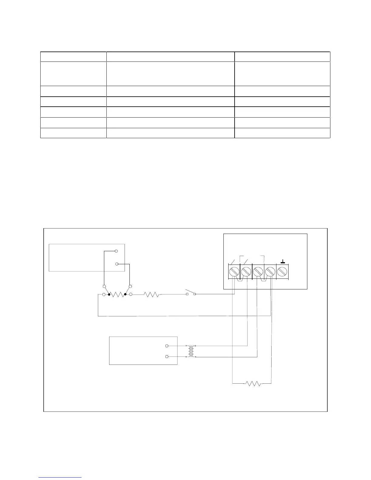
Test Setup
Figure B-1 shows the setup for the tests. Be certain to use load leads of sufficient wire gauge to carry the
full output current (see Chapter 2).
Figure B-1. Verification & Calibration Test Setup
COM
R
Rs
L
Rs = Current Monitor resistor ( 0.01 ohms )
S1
S1 = Switch is for convenience (not required).
1
30
DMM
COM
01
SENSE
R = Load resistor for CC test (20 ohms)
01
L
Rz = Impedance resistor ( 1 ohm )
R
Z
DMM
Agilent 6811B/6812B/6813B
Agilent 3458A
Agilent 3458A