Chapter 6 291
Troubleshooting the RF Section
6b. 8592L/94L, 8594Q, and 8593E/94E/95E/96E
To check control of the A3A5 input attenuator
The A7 analog interface assembly controls the three attenuator steps and
blocking capacitor in the A3A5 input attenuator using eight control lines.
Refer to the RF section block diagram for your analyzer at the end of Chapter ,
“Assembly Descriptions and Block Diagrams.” Each attenuator step requires
two control lines, as shown in Table 6-10 and Table 6-11. The attenuator is
connected to A7J5 on the A7 assembly with the ribbon cable, W36. Locate W36
using the top view of the analyzer in Chapter 11, “Major Assembly and Cable
Locations.”
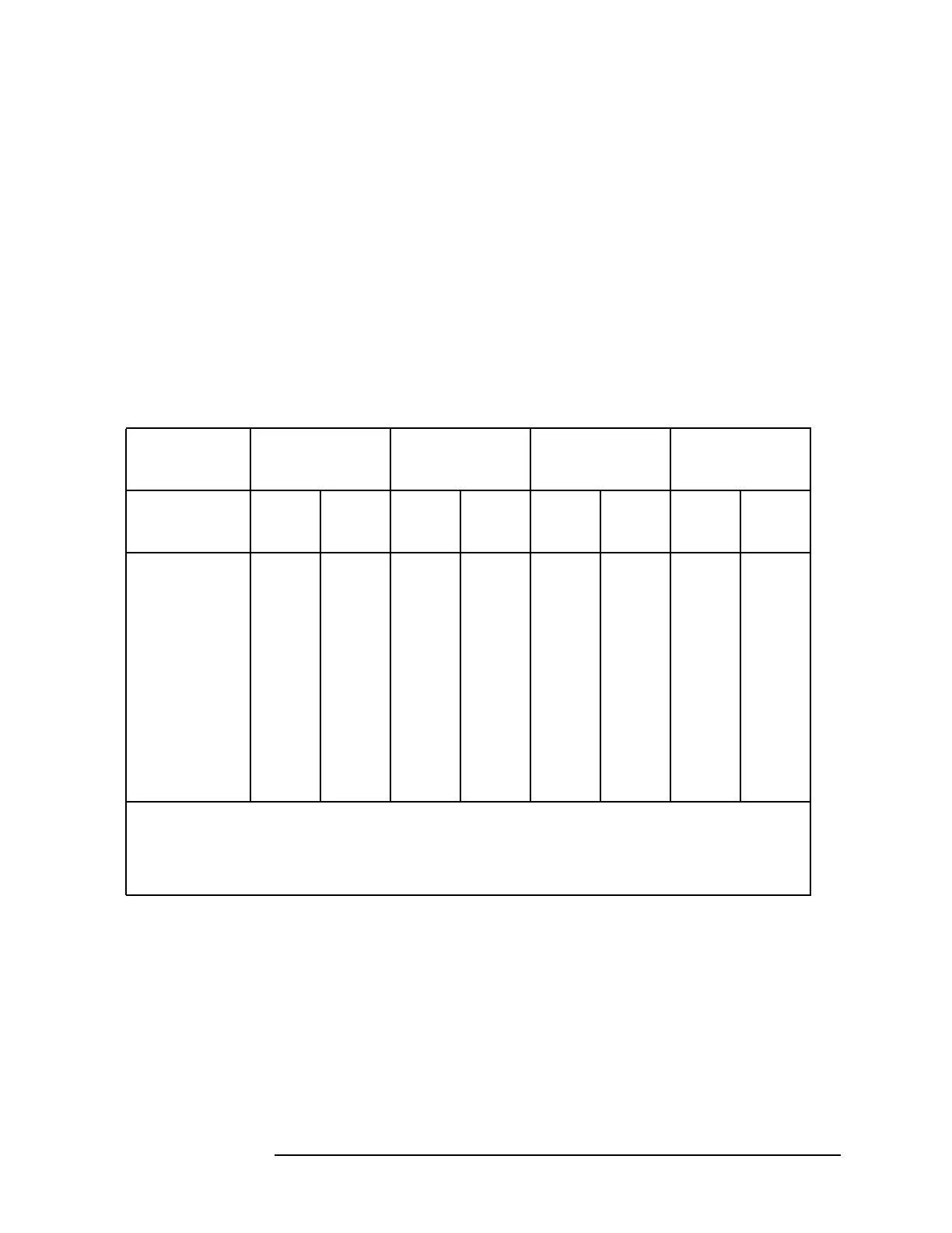
Use a digital multimeter (DMM) and the values from Table 6-10 to check the
control voltages. Measure the voltages at the A7J5 pins on the trace side of the
A7 assembly.
Table 6-10 Input Attenuator Control Output at A7J5 for 8592L and
8593E
10 dB 1st 20 dB 2nd 20 dB 3rd 20 dB
Step Step Step Step
Attenuator
Setting (dB)
Pin 2 Pin 1 Pin 9 Pin 4 Pin 8 Pin 5 Pin 7 Pin 6
0 HLHLHLHL
10 LHHLHLHL
20 HLHLLHHL
30 LHHLLHHL
40 HLLHHLLH
50 LHLHHLLH
60 HLLHLHLH
70 LHLHLHLH
H = −10 V (with the attenuator connected at A7J5)
H = 0 V (A floating output if the attenuator is disconnected.)
L = −15 V (A low at pin 2, 9, 8, or 7 indicates that the attenuator step is in the signal path.)
 Loading...

