Chapter 2 89
Making Adjustments
13. Third Converter and Second IF Bandpass
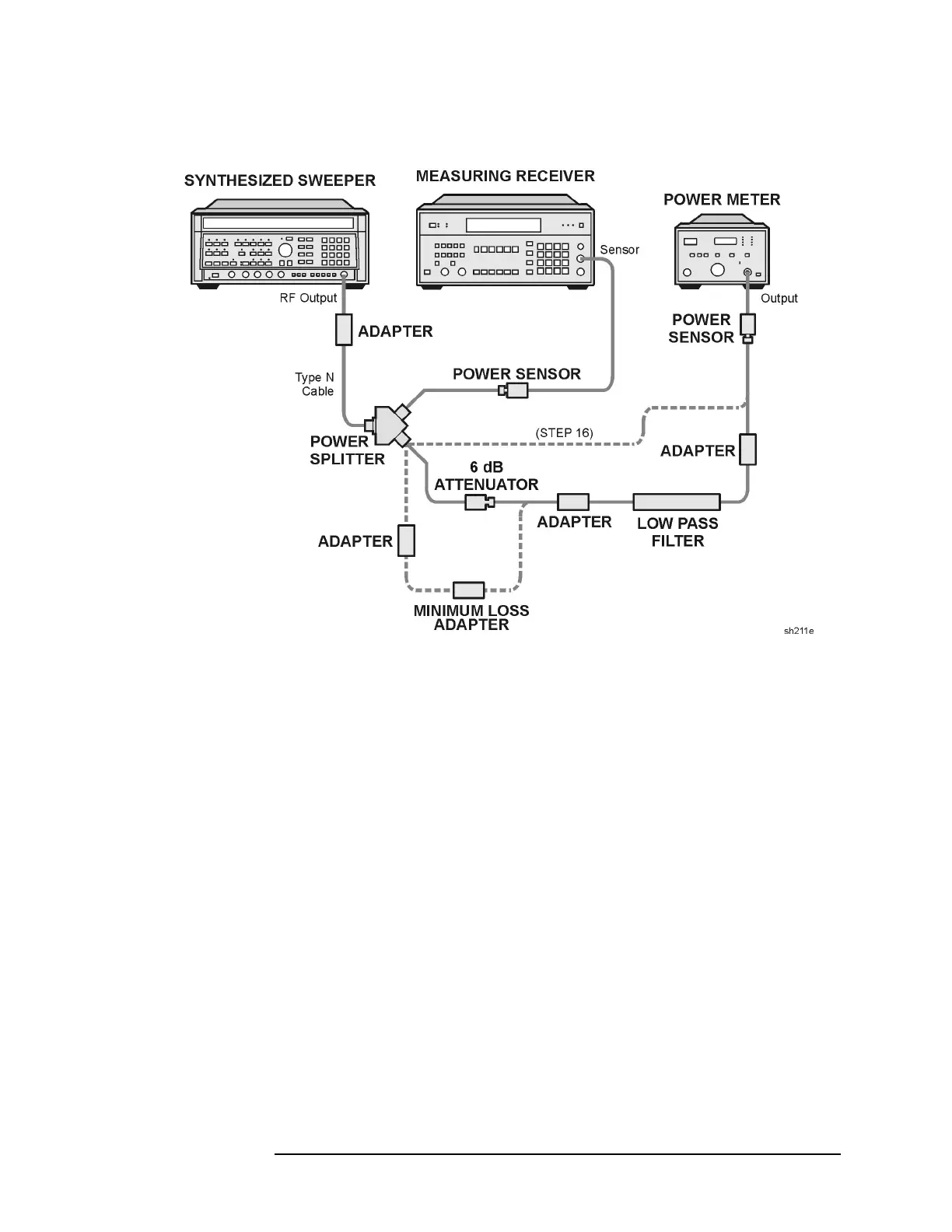
Figure 2-23 LPF Characterization
22.Press INSTRUMENT PRESET on the synthesized sweeper. Set the
controls as follows:
CW ................................................................ 300MHz
POWER LEVEL ........................................... −15dBm
23.Allow the power sensors to settle, then on the measuring receiver,
press RATIO mode. Power indication should be 0 dB.
24.On the power meter, press the dB REF mode key. Power indication
should be 0 dB.
25.Connect the LPF, Attenuator and adapters as shown in Figure 2-23.
26.Record the measuring receiver reading in dB. This is the relative
error due to mismatch.
Mismatch Error____________________dB
27.Record the power meter reading in dB. This is the relative
uncorrected insertion loss of the LPF, attenuator, and adapters.
Uncorrected Insertion Loss____________________dB
 Loading...

