100 Chapter2
Making Adjustments
15. Frequency Response of the 8590L, 8591C, and 8591E
15.On the analyzer, press FREQUENCY and ⇑ (step up), to step through
the remaining frequencies listed in Column 1 of Table 2-6. At each
new frequency repeat step 13 to step 15, entering the power sensor
Cal Factor into the measuring receiver as indicated in Column 3 of
Table 2-6.
16.On the synthesized sweeper, press CW and STEP UP.
Frequency Response Error At 4 MHz
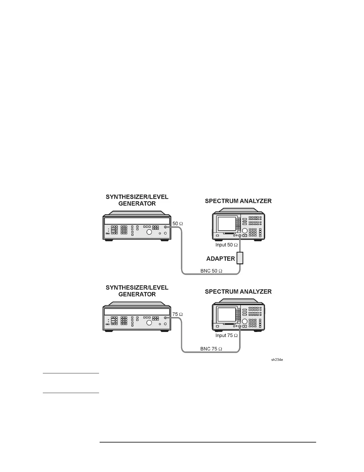
17.Using a cable, connect the frequency synthesizer directly to the
INPUT 50Ω. See Figure 2-29. For 75 Ω inputs use a 75 Ω cable to
connect the frequency synthesizer 75Ω OUTPUT to the INPUT 75Ω
of the analyzer. Set the frequency synthesizer 50–75 Ω switch to the
75 Ω position. See Figure 2-29.
Figure 2-29 Frequency Response for 4 MHz Setup
CAUTION Use only 75 Ω cables, connectors, or adapters on instruments equipped
with 75 Ω inputs or damage to the input connectors will occur.
 Loading...

