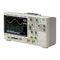
8. Multi-function Entry knob. Adjusts various settings on the oscilloscope.!
9. Meas and Cursors keys. Use these to obtain new measurements from the channel traces or
to use cursors to look at specific points on the traces.!
10. Save/Recall key. Use this to enter the Save/Recall menu when you would like to capture a
screen image of the graph and data to include in a report. !
11. USB port.!
!
!
Basic measurements!
A typical oscilloscope measurement involves a small number of steps that are used almost every
time.!
!
1. Power up!
2. Make connections from your circuit to the oscilloscope.!
3. Perform an Autoscale so that the oscilloscope will automatically acquire a trace and draw a
it on the display.!
4. Make manual adjustments to the time scale and voltage scales in order to set up for any
measurements you would like to perform on the voltage traces.!
5. (Optional) Use cursors and measurements to obtain specific voltage levels, voltage
differences and time differences from the voltage traces.!
6. Save a screen image of the graph, if needed.!
!
Each item is described below. Most of the real work occurs during step 3. However, since the
oscilloscope is doing most of that work, the step requires little explanation. Ironically, the most
mundane step, making connections, requires the longest explanation below.!
!
1. Power up!
When the oscilloscope is powered up, it will go through a boot-up cycle, enters the default
state, and waits for you to initiate a measurement. There will be a horizontal yellow line on
the display indicating that Channel 1 is turned on, but there is no voltage applied.!
!
2. Connections!
To measure voltages, you must attach leads from your circuit to the channel inputs. In
principle, you can use any channel, but typically, we make the first connection to Channel 1
and sequentially move down the line as we need more measurement points. (It will be a rare
occasion when we have an EE 201 circuit that is so complicated that we will need 4
simultaneous measurements.)!
!
There are two methods for making oscilloscope connections in EE 201 lab. The first is to use
scope probes, which are designed specifically for use with an oscilloscope. (Using the scope
probe is the way the professionals connect the oscilloscope to circuits.) A scope probe has a
BNC connector on one end that connects to the input jack of the oscilloscope, and pair of leads
at the other end for connecting into the circuit. One lead is a small alligator clip that is the
negative connection. The other lead is either a sharp probe that can be used to contact a point

 Loading...


