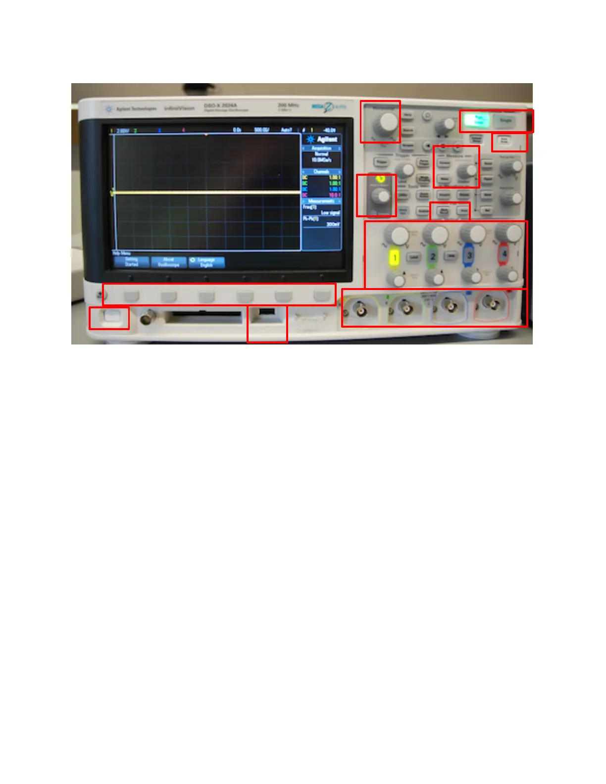
!
Figure 1. Some important items on the front panel of the Agilent DSO-X-2024A oscilloscopes
in the EE 201/230 laboratory.!
!
1. Power switch.!
2. Channel input terminals, 1 - 4. !
3. Vertical (voltage) scale and offset controls, one set for each channel. Usually, the first
signal is applied to channel 1 and channels 2-4 are added as needed for the particular
measurement. Channels are activated automatically when an Autoscale is performed.
When a channel is active, its channel button will be lit and there will be a trace on the
display for that channel. In Fig. 1 above, only channel 1 is active –#the yellow “1” is lit
while all the other channel buttons are dim. Channels can be manually activated or de-
activated by pushing the channel buttons.!
4. Horizontal (time) scale knob.!
5. Autoscale button. This causes the oscilloscope to automatically acquire a voltage signal
and draw a trace on the display. It will activate each channel where a voltage signal is
sensed. Sometimes the Autoscale activates a channel even if there are not leads attached.
Other times, a channel that should be activated may not be. You can manually activate /
de-activate channels as described in item 3 above. !
6. Run-stop and Single measurement buttons. In run mode, the oscilloscope continuously
measures and displays the voltage at the inputs. Pushing the button once causes the
measures to stop and the display will freeze with the last measured cycle of the input.
Single is used to capture a voltage transient that happens only once. !
7. Softkeys for selecting various options during oscilloscope set up. The function of the
button changes depending on what you are trying to do.!

 Loading...


