1-13
AUTO-SERIES OPERATION
Auto-series operation permits equal or proportional voltage
sharing, and allows control of output voltage from one master
unit. The voltage of the slaves is determined by the setting of the
front panel VOLTAGE control on the master and voltage divider
resistor. The master unit must be the most positive supply of the
series. The output CURRENT controls of all series units are
operative and the current limit is equal to the lowest setting. If
any output CURRENT controls are set too low, automatic cross
over to constant current operation will occur and the output volt-
age will drop. Figure 12 and Figur
e 13 show the rear panel
switch settings and terminal connections for Auto-series opera-
tion of two supplies and three supplies. This mode can also give
±
voltage tracking operation of two supplies with two separate
loads.
Mixed model numbers may be employed in auto-series combi-
nation without restriction, provided that
each slave is specified as
being capable of auto-series operation. If the master supply is set
up for constant current operation, then the master-slave combina-
tion will act as a composite constant current source.
Total output voltage to ground must not exceed 240 Vdc.
Determining Resistors. Externa
l resistors control the fraction (or
multiple) of the master unit's voltage setting that is supplied from
the slave unit. Notice that the percentage of the total output volt-
age contributed by each supply is in
dependent of the magnitude
of the total voltage. For two units in auto-series the ratio of R1 to
R2 is
(R1+R2)/R1 = (Vo/Vm)
R2/R1 = (Vs/Vm)
Where Vo = auto-series voltage = Vs + Vm
Vm = master unit's output voltage
Vs = slave unit's output voltage
For example, using the E3617A as a slave unit and putting R2=50
kΩ (1/4 w
att), then from the above equations,
R1 = R2(Vm/Vs) = 50(Vm/Vs) kΩ
In order to maintain the temperature coefficient and stability perfor-
mance of the supply, choose stable, low noise resistors.
It is recommended to connect a 0.1
μ
F capacitor in paral-
lel with R2 in two supplies operation or R2 and R4 in
thre
e supplies operation to ensure the stable operation.
Setting Voltage and Current.
Use the master unit's controls to
set the desired output voltage and current. The VOLTAGE control
of the slave unit is disabled. Turning the voltage control of the
master unit will result in a continuous variation of the output of the
series combination, with the contribution of the master's output
voltage to that of the slave's voltage always remaining in the ratio
of the external resistors. Set the CURRENT control of slave unit
above the master unit's current setting to avoid having the slave
switch to CC operation.
When in CC operation the combined output current is the same
as the master unit's curr
ent setting, and when in CV operation the
combined output voltage is the sum of the master unit's and the
slave unit's output voltages.
Overvoltage Protection. Se
t the OVP shutdown voltage in each
unit so that it shuts down at a voltage higher than its output voltage
during auto-series operation. When a master unit shuts down, it pro-
grams any slave units to zero output. When a slave unit shuts down,
it
shuts down only itself (and any slaves below it in the stack). The
master (and all slaves above the shut-down slave) continues to sup-
ply output voltage.
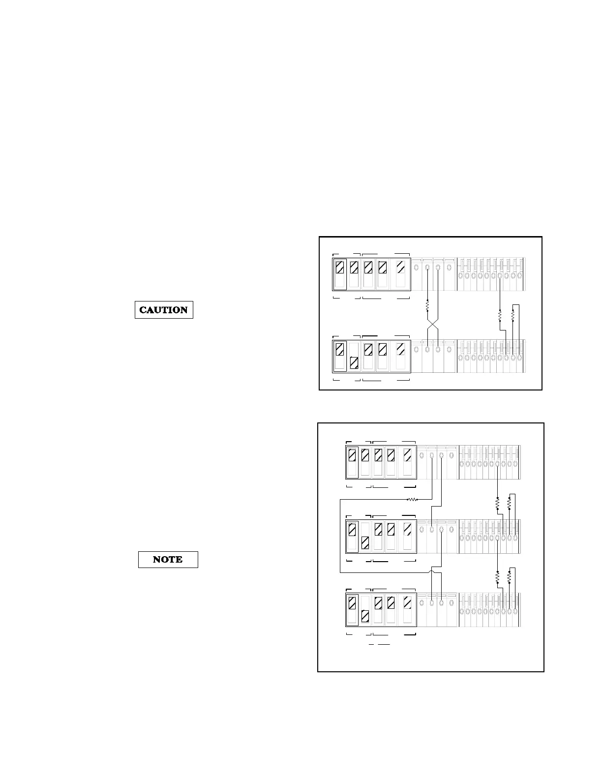
Figure 12. Auto-Series Operation of Two Supplies
Figure 13. Auto-Series Operati
on of Three Supplies
MASTER
SLAVE
CV CC SENSE
LOCAL
REMOTE
OUT
+S -S
+
_
CV CC
VREF A1 A2 A3 A4 A5
+
+
M/S 1 M/S 2
__
MASTER
SLAVE
CV CC SENSE
LOCAL
REMOTE
OUT
+S -S
+
_
CV CC
VREF A1 A2 A3 A4 A5
+
+
M/S 1 M/S 2
_
_
MASTER POWER SUPPLY
LOAD
SLAVE POWER SUPPLY
R1 R2
MASTER
SLAVE
CV CC SENSE
LOCAL
REMOTE
OUT+S
-S
+
_
CV CC
VREF
A1 A2 A3 A4 A5
+
+
M/S 1 M/S 2
__
MASTER POWER SUPPLY
LOAD
MASTER
SLAVE
CV CC SENSE
LOCAL
REMOTE
OUT
+S
-S
+
_
CV CC
VREF
A1 A2 A3 A4 A5
+
+
M/S 1 M/S 2
__
SLAVE POWER SUPPLY(S1)
MASTER
SLAVE
CV CC SENSE
LOCAL
REMOTE
OUT
+S -S
+
_
CV CC VREF A1 A2 A3 A4 A5
+
+
M/S 1 M/S 2
__
SLAVE POWER SUPPLY(S2)
R1 R2
R3 R4
Vo=Vm(1+
R2
R1
R2
R1
+
R4
R3
)
Where Vo = Auto-Series voltage = Vm + Vs1 + Vs2
Vm = master unit's output voltage
Vs1 = slave(S1) unit's output voltage
Vs2 = slave
S2
unit's out
ut volta
e

 Loading...


