1-11
Remote Programming Connections. Remote pr
ogramming
requires changing settings of the switch and connecting external
voltages to + and - terminals of "CV" or "CC" on the rear panel.
Any noise picked up on the programming leads will appear on the
supply's output and may degrade regulation. To reduce noise
pick-up, use a twisted or shielded pair of wires for programming,
with the shield grounded at one end only. Do not use the shield as
a conductor.
Notice that it is possible to oper
ate a power supply simultaneously
in the remote sensing and the remote analog programming
modes.
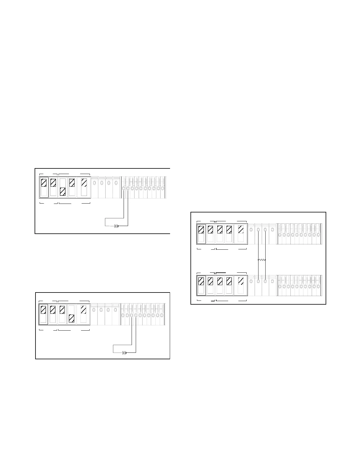
Remote Programming, Constant Voltage. Figur
e 6 shows the
rear panel switch settings and terminal connections for remote-
voltage control of output voltage. A 1 Vdc change in the remote
programming voltage produces a change in output voltage (volt-
age gain) as follows: E3614A: 0.8 Vdc, E3615A: 2 Vdc, E3616A:
3.5 Vdc, E3617A: 6 Vdc
Figure 6. Remote Voltage Programming, Constant
Voltage
Remote Programming, Constant Current. Figure 7 shows the
rear panel switch settings and terminal connections for remote-
voltage control of output current. A 1 Vdc change in the remote
programming voltage produces a change in output current (cur-
rent gain) as follows: E3614A: 0.6 Adc, E3615A: 0.3 Adc,
E3616A: 0.17 Adc, E3617A: 0.1
Adc
Figure 7. Remote Voltage Programming, Constant
Current
Remote Programming Speed. See the table of Specifications,
page 1-5.
MULTIPLE-SUPPLY OPERATION
Normal parallel and auto-parallel operation provides increased out-
put current while normal series and auto-series provides increased
o
utput voltage. Auto-tracking provides single control of output volt-
age of more than one supply. You can set up the unit for multiple-
su
pply operation by changing the settings of the rear panel switch
and connecting the leads from the rear panel terminals to the load.
Solid conductors of 0.75 to 1.5 mm
2
can be connected to the rear
panel terminals by simply push fitting. Thinner wires or conductors
are inserted into the connection space after depressing the orange
opening lever.
NORMAL PARALLEL OPERATION
Two or more power supplies being capable of CV/CC automatic
cross over operation can be connected in parallel to obtain a total
output current greater than that available from one power supply.
The total output current is the sum of the output currents of the
individual power supplies. The output of each power supply can
be set separately. The output voltage controls of one power sup-
ply should be set to the desired output voltage; the other power
supply should
be set for a slightly higher output voltage. The sup-
ply with the higher output voltage setting will deliver its constant
curr
ent output, and drop its output voltage until it equals the out-
put of the other supply, and the other supply will remain in con-
stant voltage operation and only deliver that fraction of its rated
outp
ut current which is necessary to fulfill the total load demand.
Figure 8 shows the rear panel switch settings and terminal con-
nections for normal parallel operation of two supplies.
Figure 8. Normal Parallel Operation of Two Supplies
AUTO-PARALLEL OPERATION
Auto-parallel operation permits equal current sharing under all load
conditions, and allows complete control of output current from one
master supply. The control unit is called the master; the controlled
units are called slaves. Normally, only supplies having the same
model number should be connected for auto-parallel operation,
since the supplies must have the same voltage drop across the cur-
rent monitoring resistor at full current rating. The output current of
e
ach slave is approximately equal to the master's. Figure 9 and Fig-
ure 10 show the rear panel switch settings and terminal connections
fo
r auto-parallel operation of two supplies and three supplies.
MASTER
SLAVE
CV CC SENSE
LOCAL
REMOTE
OUT
+S
-S
+
_
CV CC
VREF
A1 A2 A3 A4 A5
+
+
M/S 1 M/S 2
_
_
NOTE:
See the supplementary Manual, if you are not using
isolated programming voltage source.
MASTER
SLAVE
CV CC SENSE
LOCAL
REMOTE
OUT
+S
-S
+
_
CV CC
VREF
A1 A2 A3 A4 A5
+
+
M/S 1 M/S 2
_
_
NOTE:
See the supplementary Manual, if you are not using
isolated programming voltage source.
MASTER
SLAVE
CV CC SENSE
LOCAL
REMOTE
OUT
+S -S
+
_
CV CC
VREF A1 A2 A3 A4 A5
+
+
M/S 1 M/S 2
__
MASTER
SLAVE
CV CC SENSE
LOCAL
REMOTE
OUT
+S -S
+
_
CV CC
VREF A1 A2 A3 A4 A5
+
+
M/S 1 M/S 2
__
POWER SUPPLY
POWER SUPPLY
LOAD

 Loading...


