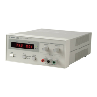
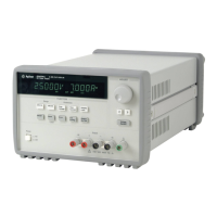
Do you have a question about the Agilent Technologies E3614A and is the answer not in the manual?
Verify product settings match line voltage and correct fuse is installed before powering.
Ensure instrument chassis and cabinet are connected to electrical ground for shock hazard prevention.
Do not operate in explosive atmospheres; avoid flammable gases or fumes.
Avoid contact with live circuits; only qualified personnel should remove covers or adjust.
Do not attempt internal service alone; ensure a qualified person is present for first aid.
Explanation of symbols like instruction manual, ground, WARNING, CAUTION, and NOTE for hazard awareness.
This manual describes all models in the Agilent E361xA 60W Bench Power Supply family.
Details Agilent E361xA compliance with various safety and EMC standards like IEC, CSA, and UL.
Explains serial number encoding, change sheets, and available product options.
Describes the power supply's suitability for bench/rack operation and its output power capabilities.
Details the input voltage, frequency, and power consumption requirements for AC input.
Covers programmable voltage/current ranges and output terminal descriptions.
Specifies performance variation due to load changes and AC line voltage variations.
Details ripple, noise, temperature coefficient, and output drift specifications.
Defines the accuracy and resolution of the front panel voltage and current displays.
Explains the built-in protection mechanisms against overloads and overvoltages.
Describes how to program output voltage using an external analog voltage source.
Explains the function and benefits of using remote sensing for load regulation.
Covers unpacking, mechanical, and electrical checks to ensure the instrument is defect-free.
Provides guidance on location, cooling, and physical dimensions for proper installation.
Details how to mount the instrument into a standard 19-inch rack.
Specifies power source compatibility and procedures for changing line voltage settings.
Explains the operating controls, indicators, and available operating modes of the instrument.
Detailed description of each control and indicator on the front panel.
Step-by-step guide to verify the instrument is operational after initial setup.
Specifies the required switch configurations on the rear panel for the initial checkout.
Details the setup for local operation using front panel controls for voltage and current.
Procedure for configuring the supply for constant voltage output.
Procedure for configuring the supply for constant current output.
Explanation and procedure for setting the OVP shutdown voltage to protect loads.
Guidelines on how to safely and effectively connect loads to the output terminals.
Information on operating the supply outside its specified performance limits.
How to use remote sensing to maintain accurate output voltage at the load.
Discusses how noise picked up on sense leads can affect output voltage regulation.
Explains potential stability issues and how to mitigate them when using remote sensing.
Details connection procedures and impact on constant voltage regulation.
How to control output voltage and current using an external analog voltage source.
Connecting multiple supplies in parallel to increase total output current.
Configuration for equal current sharing among supplies in parallel operation.
Procedures for setting master and slave units for auto-series operation.
Guidance on setting OVP for safe auto-series operation.
How to implement remote sensing and analog programming with auto-series.
Calculations for external resistors needed for proportional voltage tracking.
Procedures to set up voltage and current controls for master and slave units.
Details on OVP settings, remote sensing, and analog programming for tracking.
How the power supply responds to pulsed load currents and potential crossover.
Methods to prevent damage from reverse current flow from the load.
The role of output capacitance in supplying pulses and its effect on current limiting.
Protection mechanisms against reverse voltage applied to output terminals.
Recommended circuit and precautions for using the supply to charge batteries.
An overview of the power supply's internal functional blocks and signal paths.
Overview of maintenance, calibration, and troubleshooting procedures.
Lists essential test equipment needed for performing maintenance tasks.
Basic tests to confirm proper functionality before in-depth testing.
Guidelines on how to properly connect test equipment for accurate measurements.
Benefits and usage of electronic loads in performance testing.
Proper connection of the sampling resistor for accurate current measurement.
Procedure for setting up tests to evaluate constant voltage performance.
Measuring output voltage stability under varying load conditions.
Measuring output voltage stability under varying AC input line voltages.
Measuring how quickly the output voltage recovers from load changes.
Method for measuring the root-mean-square (RMS) value of output ripple and noise.
Method for measuring the peak-to-peak value of output ripple and noise.
Procedures for testing constant current performance, including setup and regulation.
Steps for performing adjustments and calibrations after testing or repairs.
General steps to follow for diagnosing and resolving power supply faults.
Specific checks for issues within the reference and bias voltage circuits.
Methods for diagnosing problems within the series and preregulator feedback loops.
Information on how to identify and order replacement components for the unit.
List of standard reference designators used for components in the manual.
Instructions on how to place orders for replacement parts with Agilent Technologies.
Explains remote analog programming for controlling output voltage or current using external sources.
Details how to program constant voltage output using analog sources.
Diagram and explanation for connecting programming voltage to the positive output terminal.
Diagram and explanation for connecting programming voltage to the negative output terminal.
Method for using external resistors to control output voltage.
Diagram and explanation for using resistors with common negative output connection.
How to achieve constant current output using an analog voltage source.
How to achieve constant current output using an analog current source.
Method to increase programming currents by adding resistors.
How to monitor the power supply's output current using internal resistors.
Setup for connecting external resistors for remote programming.
Procedure for controlling constant voltage output using external resistors.
Procedure for controlling constant current output using external resistors.
Agilent's certification of product specifications and calibration traceability.
Details the warranty period and coverage for Agilent hardware and software products.
Defines conditions that void the warranty and available customer remedies.
Information on obtaining technical support and assistance from Agilent.
Statement of compliance with EMC Directive 89/336/EEC and related product standards.
Statement of compliance with Low Voltage Directive 73/23/EEC and safety standards.
Information on the competent body that assessed the product's conformity.
| Brand | Agilent Technologies |
|---|---|
| Model | E3614A |
| Category | Power Supply |
| Language | English |
