1-10
pl
above 100% rated output. Limit
our pro
rammin
volta
e to 10 Vdc.
Remote Pro
rammin
Connections. Remote pro
rammin
requires chan
in
settin
s of the switch and connectin
external
volta
es to + and - terminals of "CV" or "CC" on the rear panel.
An
noise picked up on the pro
rammin
leads will appear on the
suppl
's output and ma
de
rade re
ulation. To reduce noise
pick-up, use a twisted or shielded pair of wires for pro
rammin
,
with the shield
rounded at one end onl
. Do not use the shield as
a conductor.
Notice that it is possible to operate a power suppl
simulta-
neousl
in the remote sensin
and the remote analo
pro
ram-
min
modes.
Remote Pro
rammin
, Constant Volta
e. Fi
ure 6 shows the
rear panel switch settin
s and terminal connections for remote-
volta
e control of output volta
e. A 1 Vdc chan
e in the remote
pro
rammin
volta
e produces a chan
e in output volta
e (volt-
a
e
ain) as follows: E3614A: 0.8 Vdc, E3615A: 2 Vdc, E3616A:
3.5 Vdc, E3617A: 6 Vdc
Fi
ure 6. Remote Volta
e Pro
rammin
, Constant
Volta
e
Remote Pro
rammin
, Constant Current. Fi
ure 7 shows the
rear panel switch settin
s and terminal connections for remote-
volta
e control of output current. A 1 Vdc chan
e in the remote
pro
rammin
volta
e produces a chan
e in output current (cur-
rent
ain) as follows: E3614A: 0.6 Adc, E3615A: 0.3 Adc,
E3616A: 0.17 Adc, E3617A: 0.1 Adc
Fi
ure 7. Remote Volta
e Pro
rammin
, Constant
Current
Remote Pro
rammin
Speed. See the table of Specifications,
pa
e 1-5.
MULTIPLE-SUPPLY OPERATION
Normal parallel and auto-parallel operation provides increased out-
put current while normal series and auto-series provides increased
output volta
e. Auto-trackin
provides sin
le control of output volt-
a
e of more than one suppl
. You can set up the unit for multiple-
suppl
operation b
chan
in
the settin
s of the rear panel switch
and connectin
the leads from the rear panel terminals to the load.
Solid conductors of 0.75 to 1.5 mm
2
can be connected to the rear
panel terminals b
simpl
push fittin
. Thinner wires or conductors
are inserted into the connection space after depressin
the oran
e
openin
lever.
NORMAL PARALLEL OPERATION
Two or more power supplies bein
capable of CV/CC automatic
cross over operation can be connected in parallel to obtain a total
output current
reater than that available from one power suppl
.
The total output current is the sum of the output currents of the
individual power supplies. The output of each power suppl
can
be set separatel
. The output volta
e controls of one power sup-
pl
should be set to the desired output volta
e; the other power
suppl
should be set for a sli
htl
hi
her output volta
e. The sup-
pl
with the hi
her output volta
e settin
will deliver its constant
current output, and drop its output volta
e until it equals the out-
put of the other suppl
, and the other suppl
will remain in con-
stant volta
e operation and onl
deliver that fraction of its rated
output current which is necessar
to fulfill the total load demand.
Fi
ure 8 shows the rear panel switch settin
s and terminal con-
nections for normal parallel operation of two supplies.
Fi
ure 8. Normal Parallel Operation of Two Supplies
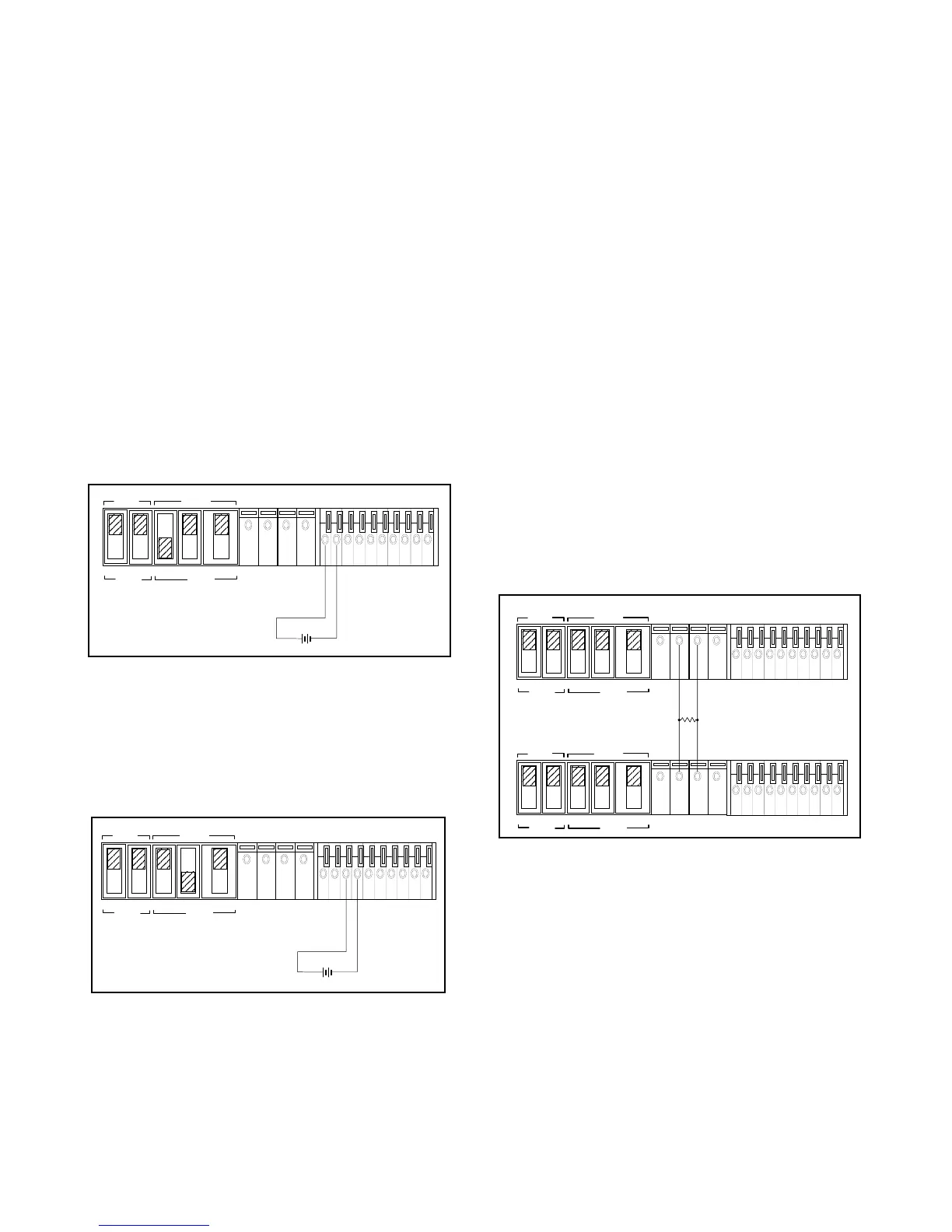
AUTO-PARALLEL OPERATION
Auto-parallel operation permits equal current sharin
under all load
conditions, and allows complete control of output current from one
master suppl
. The control unit is called the master; the controlled
units are called slaves. Normall
, onl
supplies havin
the same
model number should be connected for auto-parallel operation,
since the supplies must have the same volta
e drop across the cur-
rent monitorin
resistor at full current ratin
. The output current of
each slave is approximatel
equal to the master's. Fi
ure 9 and Fi
-
ure 10 show the rear panel switch settin
s and terminal connections
for auto-parallel operation of two supplies and three supplies.
MASTER
SLAVE
CV CC SENSE
LOCAL
REMOTE
OUT
+S
-S
+
_
CV CC
VREF
A1 A2 A3 A4 A5
+
+
M/S 1 M/S 2
_
_
NOTE:
See the supplementar
Manual, if
ou are not usin
isolated pro
rammin
volta
e source.
MASTER
SLAVE
CV CC SENSE
LOCAL
REMOTE
OUT
+S
-S
+
_
CV CC
VREF
A1 A2 A3 A4 A5
+
+
M/S 1 M/S 2
_
_
NOTE:
See the supplementar
Manual, if
ou are not usin
isolated pro
rammin
volta
e source.
MASTER
SLAVE
CV CC SENSE
LOCAL
REMOTE
OUT
+S -S
+
_
CV CC
VREF
A1 A2 A3 A4 A5
+
+
M/S 1 M/S 2
__
MASTER
SLAVE
CV CC SENSE
LOCAL
REMOTE
OUT
+S
-S
+
_
CV CC
VREF
A1 A2 A3 A4 A5
+
+
M/S 1 M/S 2
_
_
POWER SUPPLY
POWER SUPPLY
LOAD