A-7
e. Record output volta
e across Rs and convert it to
current b
dividin
this volta
e b
Rs.
f. Adjust autotransformer to the hi
h line volta
e (127
Vac for nominal 115 Vac, 110 Vac for nominal 100
Vac, and 253 Vac for nominal 230 Vac).
. When the readin
settles, record the volta
e across
Rs a
ain and convert it current. Check that the two
recorded readin
s differ less than 0.01% of output
current plus 250 µA.
PARD(Ripple and Noise)
Definition : The residual ac current which is superimposed
on the dc output current of a power suppl
. Constant current
PARD is specified as the root-mean-square(rms) output cur-
rent in a frequenc
ran
e of 20 Hz to 20 MHz with the suppl
in CC operation.
PARD(RMS) Measurement
Test Parameter:
Measured Variable: Output Current(rms)
Expected Results: E3614A: Less than 5 mA rms
E3615A: Less than 2 mA rms
E3616A: Less than 500 µA rms
E3617A: Less than 500 µA rms
Test Procedure:
a. Connect the test equipment as shown in Fi
ure A-8.
b. Turn the suppl
's power on and turn VOLTAGE con-
trol full
clockwise.
c. Turn up output current to the full rated value. Check
that the CC indicator remains li
hted. Reduce CUR-
RENT control if not li
hted.
d. Record rms volta
e across Rs and convert it to cur-
rent b
dividin
this volta
e b
Rs.
e. Check that the rms noise current is less than 5 mA
rms for E3614A, 2 mA rms for E3615A and 500 µA
rms for E3616A and E3617A respectivel
.
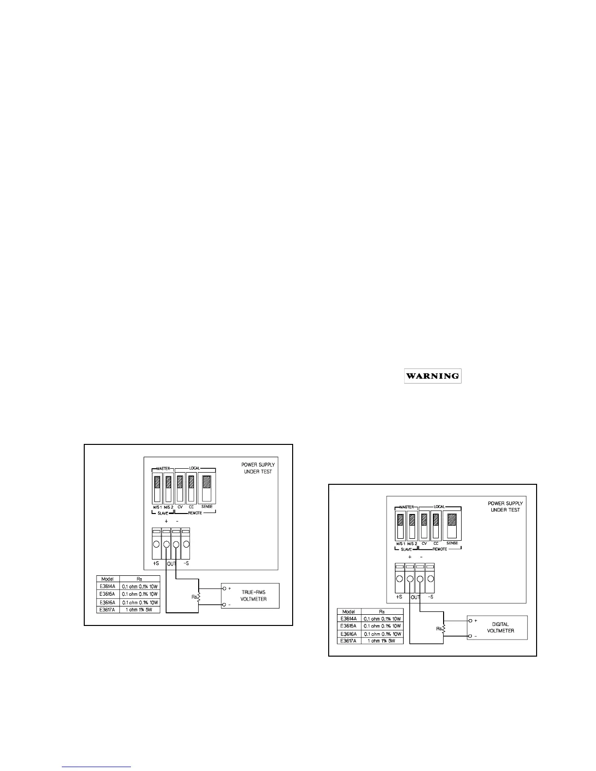
Fi
ure A-8. CC PARD RMS Measurement Test Setup
CC Drift (Stability)
Definition: The chan
e in output current for the first 8 hours fol-
lowin
a 30-minute warm-up with constant input line volta
e,
constant load resistance and constant ambient temperature.
Test Parameter:
Measured Variable: Output Current
Expected Results: Less than 0.1% plus 10 mA
Test Procedure:
a. Connect the DVM across Rs in Fi
ure A-4. Operate
the electronic load in constant volta
e mode and set
its volta
e to the full rated value of the power suppl
.
b. Turn the suppl
's power on and turn VOLTAGE con-
trol full
clockwise.
c. Turn up output current to the full rated value.
d. After a 30-minute warm-up, note the volta
e on DVM
and convert it to current b
dividin
this volta
e b
Rs.
e. The converted output current should deviate less than
0.1% plus 10 mA from the current obtained in step d
over a period of 8 hours.
ADJUSTMENT AND CALIBRATION
PROCEDURE
Adjustment and calibration ma
be required after perfor-
mance testin
, troubleshootin
, or repair and replacement.
Perform those adjustments that affect the operation of the
fault
circuit and no others. To remove the top cover, refer to
"Line Volta
e Option Conversion" para
raph.
Maintenance described herein is performed with
power supplied to the suppl
, and protective covers
removed. Such maintenance should be performed
onl
service-trained personnel who are aware of the
hazards involved (for example, fire and electrical
shock). Where maintenance can be performed with-
out power applied, the power should be removed.
Fi
ure A-9. Calibration Test Setup

 Loading...


