A-6
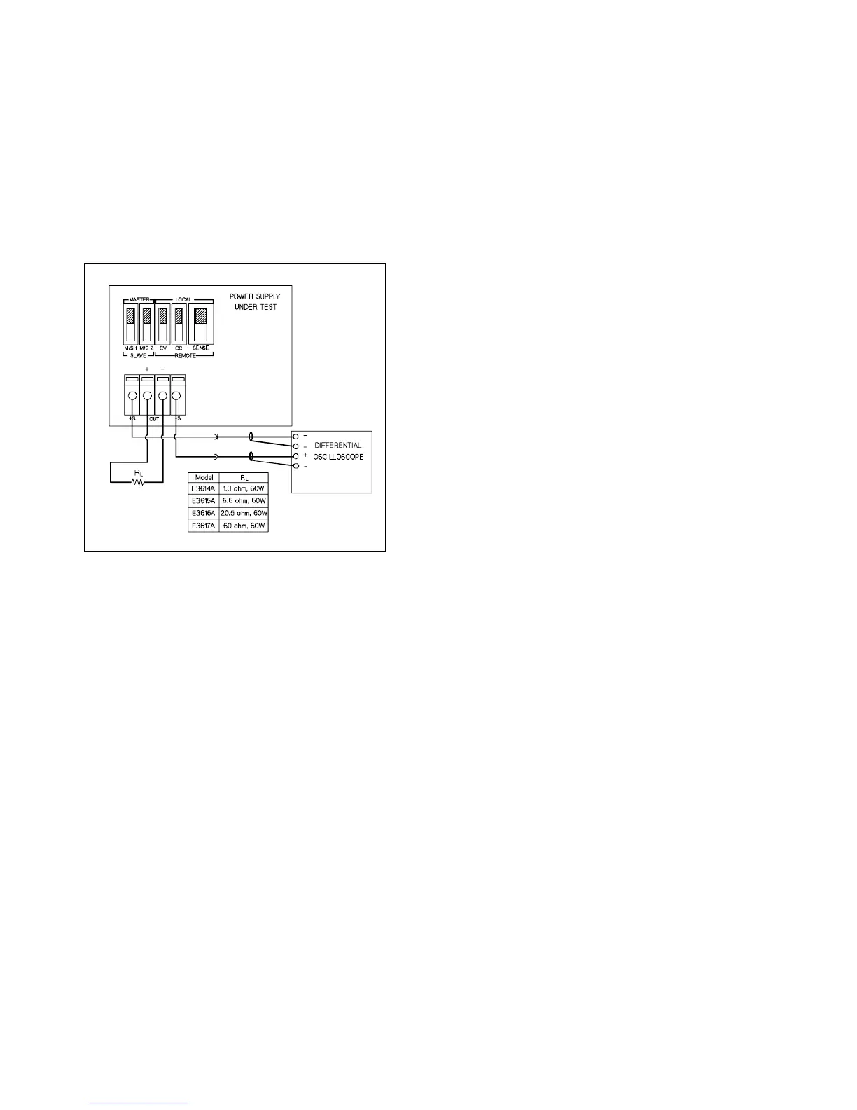
a. Connect the test equipment as shown in Fi
ure A-7.
b. Turn the suppl
's power on and turn CURRENT con-
trol full
clockwise.
c. Turn up output volta
e to the full rated value. Check
that the suppl
's CV indicator remains li
hted.
Reduce VOLTAGE control if not li
hted.
d. Set the oscilloscope to AC mode and bandwidth to 20
MHz.
e. Check that the peak-to-peak noise is less than 1 mV.
Fi
ure A-7.
B
CV PARD Peak-to-Peak Measurement Test
Setup
CV Drift (Stability)
Definition: The chan
e in output volta
e (dc to 20 Hz) for the
first 8 hours followin
a 30-minute warm-up period with con-
stant input line volta
e, constant load resistance and constant
ambient temperature.
Test Parameter:
Measured Variable: Output Volta
e
Expected Results: Less than 0.1% plus 5 mV
Test Procedure:
a. Connect the DVM across Rs in Fi
ure A-4.
b. Operate the electronic load in constant current mode
and set its current to the full rated value of power sup-
pl
.
c. Turn the suppl
's power on and turn CURRENT con-
trol full
clockwise.
d. Turn up output volta
e to the full rated value as read
on the di
ital voltmeter.
e. After a 30-minute warm-up, note the volta
e on DVM.
f. The output volta
e readin
should deviate less than
0.1% plus 5 mV from the readin
obtained in step e
over a period of 8 hours.
CONSTANT CURRENT (CC) TESTS
CC Setup. Constant current tests are analo
ous to constant
volta
e tests, with the suppl
's output short circuited and the
volta
e set to full output to assure CC operation. For output
current measurements the current monitorin
resistor must
be treated as a four terminal device. Refer to the "Measure-
ment Techniques" for details. All constant current measure-
ments are made in terms of the chan
e in volta
e across this
resistor; the current performance is calculated b
dividin
these volta
e chan
es b
ohmic value of Rs.
Load Re
ulation (Load Effect)
Definition: CC Load re
ulation is the chan
e in the stead
state
value of dc output current due to a chan
e in load resistance
from short circuit to full load or from full load to short circuit.
Test Parameter:
Measured Variable: Output Current
Expected Results: Less than 0.01% plus 250 µA
Test Procedure:
a. Connect the DVM across Rs in Fi
ure A-4. Operate
the electronic load in constant volta
e mode and set
its volta
e to the full rated value of power suppl
.
b. Turn the suppl
's power on and turn VOLTAGE con-
trol full
clockwise.
c. Turn up output current to the full rated value. Check
that the AMPS displa
reads full rated values and CC
indicator remains li
hted. Reduce CURRENT control
if not li
hted.
d. Record the volta
e across Rs and convert it to cur-
rent b
dividin
this volta
e b
Rs.
e. Operate the electronic load in short (input short)
mode.
f. When the readin
settles, record volta
e across Rs
a
ain and convert it current. Check that the two
recorded readin
s differ less than 0.01% of output
current plus 250 µA.
Line Re
ulation (Source Effect)
Definition:
Line re
ulation is the chan
e in the stead
state
value of dc output current due to a chan
e in ac input volta
e
from the minimum to maximum value(±10% of nominal volta
e).
Test Parameter:
Measured Variable: Output Current
Expected Results: Less than 0.01% plus 250 µA
Test Procedure:
a. Connect the DVM across Rs in Fi
ure A-4. Operate
the electronic load in constant volta
e mode and set
its volta
e to the full rated value of power suppl
.
b. Connect the suppl
to the ac power line throu
h a
variable autotransformer that set for low line volt-
a
e(104 Vac for nominal 115 Vac, 90 Vac for nominal
100 Vac, and 207 Vac for nominal 230 Vac).
c. Turn the suppl
's power on and turn VOLTAGE con-
trol full
clockwise.
d. Turn up output current to the full rated value. Check
that the AMPS displa
reads full rated values and CC
indicator remains li
hted. Reduce CURRENT control
if not li
hted.