1-10-5
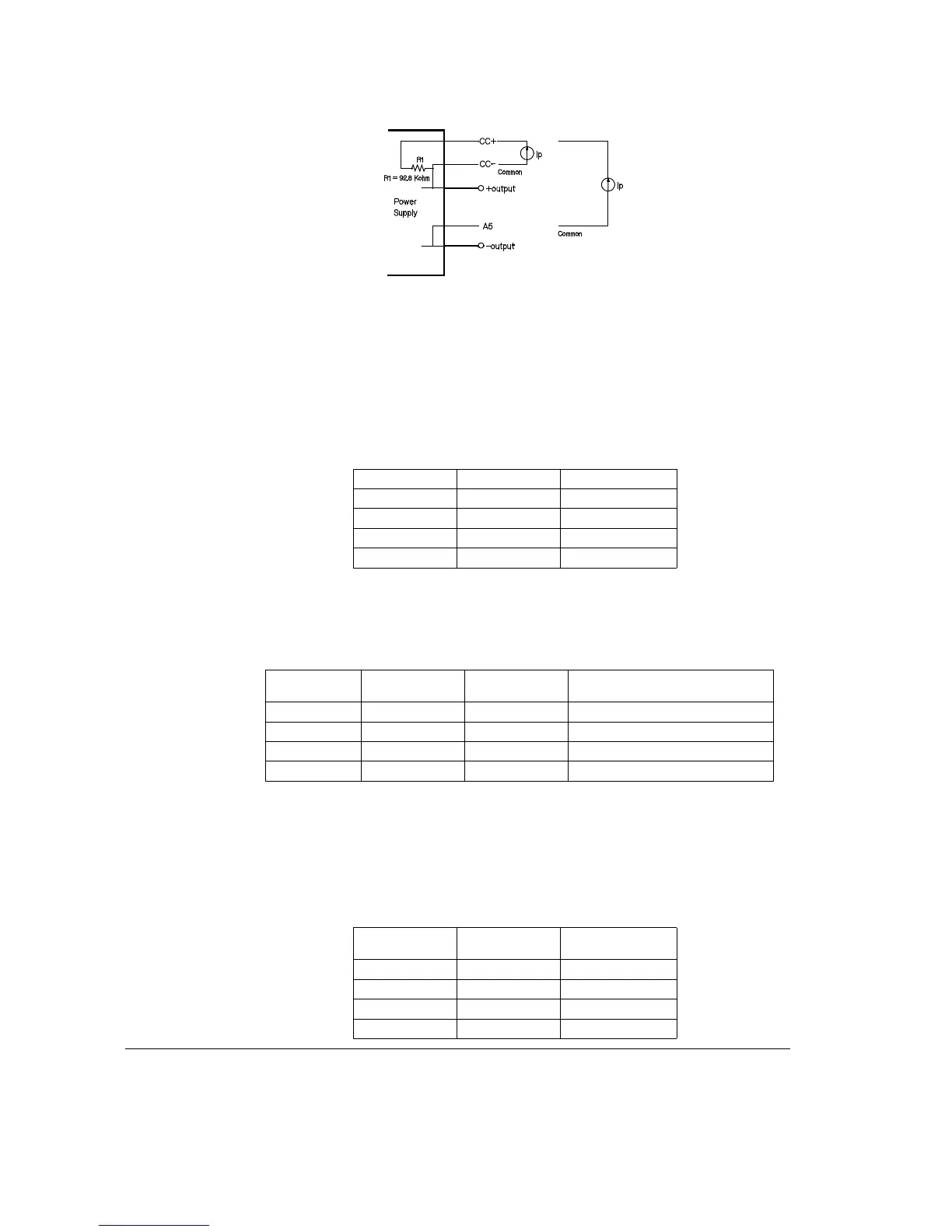
Figure 6
Set the CC switch down, and all others up.
I
in
= 1/A x I
out
I
out
= A x V
in
Where I
out
is the power supply output current in amps.
I
in
is the programming current in µamps.
A is the gain.
Programming currents can be increased by adding a resistor across the CC+ and CC-. A
10 volts drop across R1 represents full scale current of the power supply. When a 1 kohm
resistor is added across R1, the programming currents are as follows with the
programming current in mA.
Current Monitoring
Current of the power supply can be monitored across the internal current monitoring
resistor. One side of the resistor is at the +output and A3; the other side of the resistor
is at A1. The table below shows the resistor value and conversion factors. To obtain
the current divide the measured voltage by the resistor value or multiply the amps/V
times the voltage measured.
Model A (A/µA) 1/A (µV/A)
E3614A 0.055 18
E3515A 0.0278 35.9
E3616A 0.0158 63.4
E3617A 0.00928 108
Model A (A/mV) 1/A (mA/A)
Parallel resistor required for a
1 amp/mamp value of A (kohm)
E3614A 0.594 1.69 1.7
E3515A 0.297 3.37 3.45
E3616A 0.168 5.95 6.28
E3617A 0.0989 1.01 11.2
Model
Resistor
value (
Ω)
amps/V
E3614A 0.1 10
E3515A 0.2 5
E3616A 0.6 1.67
E3617A 0.89 1.12