EasyManuals Logo

Agilent Technologies E3614A User Manual

Agilent Technologies E3614A
47 pages
To Next Page IconTo Next Page
To Previous Page IconTo Previous Page
Page #41 background imageLoading...
Page #41 background image
1-10-3
Programming Voltage Common to the Minus Output
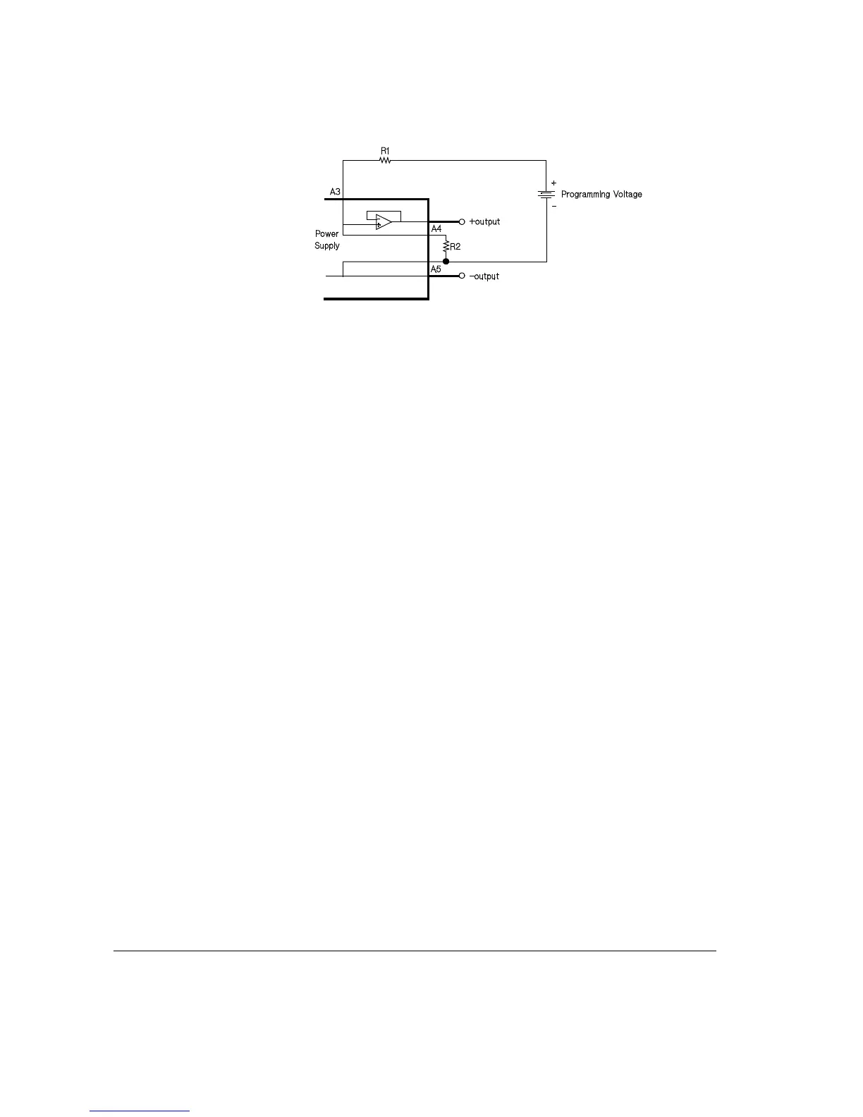
Figure 4
The output will always be the same or less than the programming voltage.
The M/S2 switch must be in the down position. For best results, place a 0.1µF capacitor
in parallel with R2.
V
in
= (R1R2) / R2 x V
out
V
out
= R2 / R1+R2) x V
in
Where V
out
is the power supply output voltage.
V
in
is the programming voltage.
R1 and R2 should be in the 1K to 100K range.

Questions and Answers:

Question and Answer IconNeed help?

Do you have a question about the Agilent Technologies E3614A and is the answer not in the manual?

Agilent Technologies E3614A Specifications

General IconGeneral
BrandAgilent Technologies
ModelE3614A
CategoryPower Supply
LanguageEnglish

Related product manuals