A-9
After the trouble has been isolated to one of the feedback
loops, troubleshootin
can proceed as described in Tables A-
4, A-5, or A-6.
Series Re
ulatin
Feedback Loop. When troubleshootin
the series re
ulatin
loop, it is useful to open the loop since
measurements made an
where within a closed loop ma
appear abnormal. With a loop closed, it is ver
difficult to sep-
arate cause from effect. As described in Tables A-4 and A-5,
the conduction or cutoff capabilit
of each sta
e is checked
b
shortin
or openin
a previous sta
e, as follows:
1. Shortin
the emitter to collector of a transistor simu-
lates saturation, or the full ON condition.
2. Shortin
the emitter to base of a transistor cuts it off,
and simulates an open circuit between emitter and
collector.
Althou
h a lo
ical first choice mi
ht be to break the loop
somewhere near its mid-point, and then perform successive
subdividin
tests, it is more useful to trace the loop from the
series re
ulator backwards a sta
e at a time, since loop fail-
ures occur more often at the hi
her power levels.
Prere
ulator Feedback Loop. The prere
ulator feedback
loop (SCR control circuit) can be convenientl
checked usin
Table A-6. As indicated in Table A-6, the control circuit is
checked b
startin
with the waveform at point 7 and point 6
(shown on the schematic dia
ram) and tracin
forwards and
backwards from this point.
Overvolta
e Protection Circuit Troubles
When troubleshootin
the overvolta
e protection circuit, it is
useful to check the turn-on overshoot control circuit which
includes U20 and Q10. The function of the control circuit is to
slow down the risin
speed of the +15 V bias the moment the
power is turned on. This function prevents the suppl
from
false OVP trippin
the moment the power is turned on. After
the troubles has been isolated to overvolta
e protection cir-
cuit, troubleshootin
can proceed as described in Table A-7.
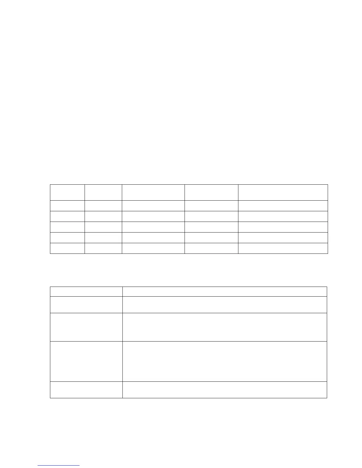
Table A-2. Reference and Bias Circuit Troubleshootin
METER
COMMON
METER
POSITIVE
NORMAL INDICATION NORMAL RIPPLE
(p-p)
PROBABLE CAUSE
TP6 point 2 +15.0 +/- 0.3 Vdc 2 mV Check U13, CR31, and CR32.
TP6 point 4 -12.0 +/- 0.3 Vdc 2 mV Check +15 V bias or U14.
TP6 TP7 +10.5 +/- 0.2 Vdc 2 mV Check +15 V bias, U11, and U14.
TP6 point 3 -5.1 +/- 0.5 Vdc 2 mV Check -12 V bias or VR1.
TP6 point 5 +5.0 +/- 0.3 Vdc 4 mV Check U1 and CR2.
Table A-3. Overall Troubleshootin
SYMPTOM CHECKS AND PROBABLE CAUSES
Hi
h Output Volta
e a. Check series re
ulator feedback loop or prere
ulator feedback loop.
b. Refer to "Re
ulatin
Loop Troubles" para
raph or Table A-4 or A-6 as instructed.
Low and No Output Volta
e a. If output is zero, check fuse.
b. Check series re
ulator feedback loop or prere
ulator loop.
Refer to "Re
ulatin
Loop Troubles" para
raph or Table A-5 or A-6 as instructed.
c. Check CR20 shorted.
Hi
h Ripple a. Check operatin
setup for
round loops.
b. If output floatin
, connect 1 µF capacitor between output and
round.
c. Ensure that the suppl
is not crossin
over to constant current mode
under loaded conditions.
d. Check for low volta
e across C7 or Q1 and Q4.
e. Check for excessive ripple on reference volta
es (Table A-2).
Poor Line Re
ulation
(Constant Volta
e)
a. Check +10 V reference volta
e.
b. Check U9.