2
A3 RF Functionality
E7495A/B Manual Verification
Verifying the E7495A/B RF Functionality
The base product of the E7495A/B consists of two main blocks: Source
and Receiver. The antenna/cable measurements use both of these blocks
and, using the Insertion Loss and Return Loss measurements, verify
the correct operation of both the source and receiver.
Test equipment
• 2 - 10 dB Type-N pads (Part of E7495A/B Cal kit)
• Short Type-N cable (Part of E7495A/B Cal kit)
• 6, 20, and 30 dB 849xx series Type-N pads or a 10 dB step attenuator
Insertion loss procedure
1. Press [MODE] Antenna/Cable, Two Port Insertion Loss.
2. Set the Start Frequency to 375 MHz; Stop Frequency to 2500 MHz.
3. Press Setup, Optimize and verify it is set to Accuracy.
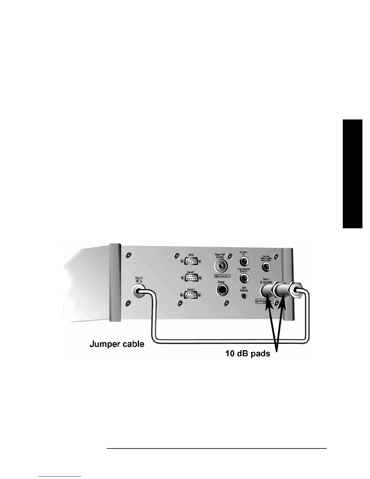
4. Connect the two 10 dB pads and a short Type-N cable as shown in
Figure 1 on page 2.
Figure 1 Connect the 10 dB pads.