01
09
11
10
12
02
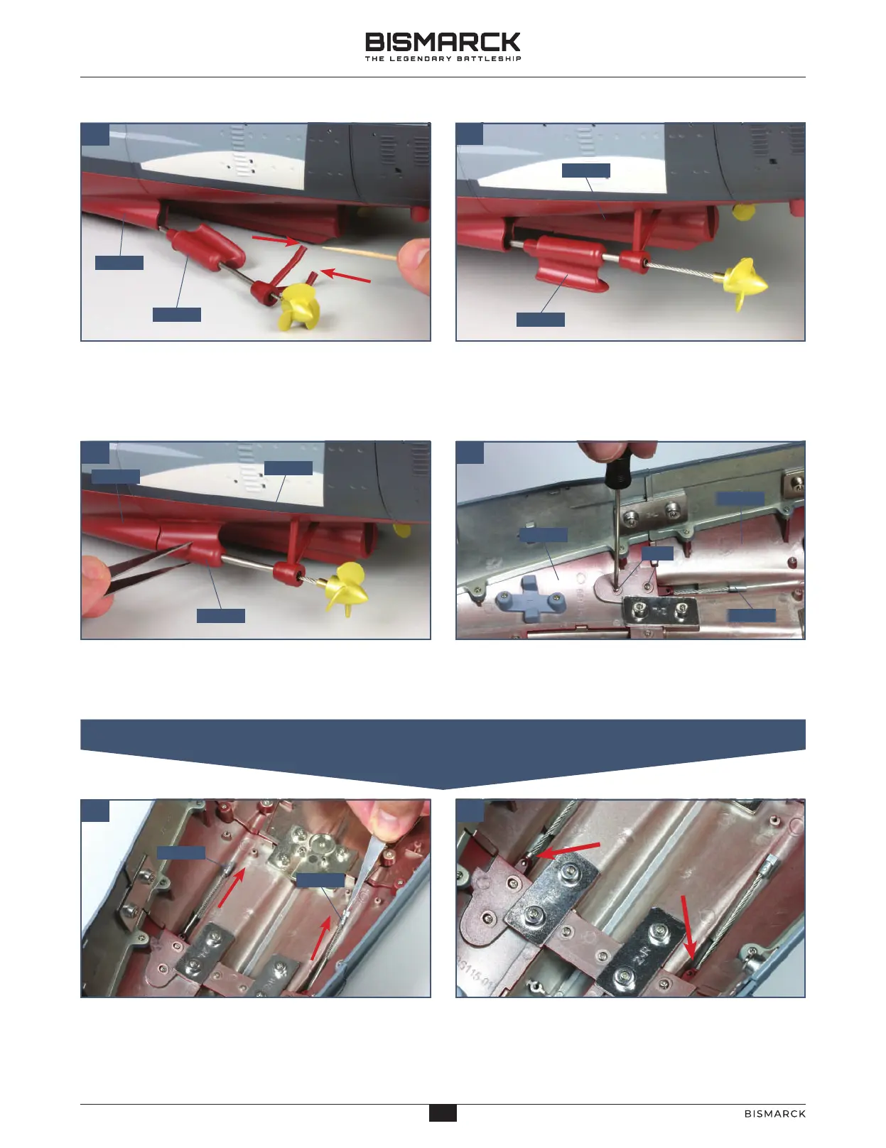
Turning to the port side of the hull, insert the shaft
of propeller 120-01 into the opening on the port
side of keel section 111-01. Apply some glue to
the two ends of the shaft bracket (arrows).
Push the propeller assembly 120-01 in place so that
the two ends of the shaft bracket can be glued into
the holes in keel section 115-01.
Turn the support on the propeller 120-01 so that
the flat side is against the hull and slide it forwards,
against the opening in keel section 111-01.
Working from inside the hull, fix the support of
the propeller 120-01 in place with two 2 x 4mm PM
screws, as shown.
Pull the ends of the propeller shafts 120-01 and
120-02 forwards as far as possible along the channels
in the keel section (arrows).
At the same time, the fine metal sleeves on the
shafts (indicated by the arrows) should be pushed
aft as far as possible.
12001
11101
12001
11501
12001
11501
11101
12001
PM
11501
11101
12001
12002
02. FIXING THE ENDS OF THE SHAFTS IN PLACE
17
16
AGORAMODELS BISMARCK
17
AGORAMODELS BISMARCK