01 02
01. PREPARATORY WORK
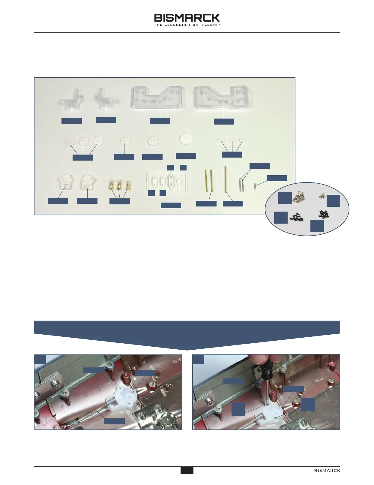
COMPONENTS CHECKLIST
122-01: Port gearbox support
122-02: Starboard gearbox
support
122-03: Upper part
of the gearbox
122-04: Lower part
of the gearbox
122-05: Three cogs
122-06: Cog
122-07: Cog
122-08: Cog
122-09: Three small cogs
122-10: Port cog and
pin housing
122-11: Starboard cog
and pin housing
122-12: Three pivot pins
122-13: Three grips and
a bracket
122-14: Two cog shafts
122-15: Cog shaft
122-16: Two cog shafts
122-17: Cog shaft
Thirteen 2 x 4mm PM screws
Four 2 x 3mm PM screws
Nine 2 x 4mm PB screws
Seven 2 x 6mm PB screws
Place the port cog housing 122-10 (labelled L) in front
of the port propeller shaft 120-01, fitting it onto the
two raised screw sockets on the keel 111-01, as shown.
Fix the port cog housing 122-10 to the keel section
111-01 using two 2 x 4mm PM screws.
12201
PM
2 x 4
PM
2 x 3
PB
2 x 4
PB
2 x 6
12202
12203
12204
12206
12205
12207
12208
12209
12210
12211
12213
12212
12214 12215
12216
12217
C
A B
D
PM
2 x 4
12210
12001
11101
11101
12210
PM
2 x 4
STAGE 122
THE GEARBOX FOR THE PROPELLERS
20
20
AGORAMODELS BISMARCK
PB
AGORAMODELS BISMARCK
 Loading...