09
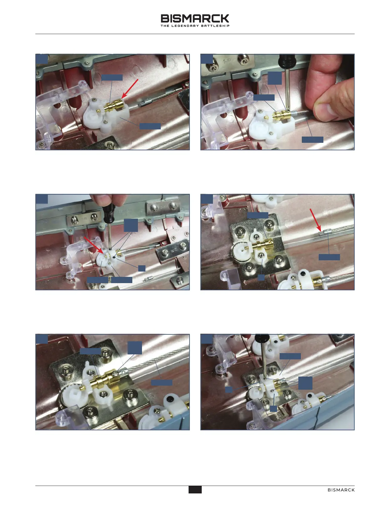
Similarly on the starboard side, fit the pivot pin 122-12
into the cog housing 122-11. Make sure that the hole in
part 122-12 faces upwards (arrow). (The hull is viewed
from the other side to the previous step.)
Fit the end of the propeller shaft 120-02 into part
122-12, with the flat side facing upwards. Fix in place
with a 2 x 3mm PM screw.
05 06
Take the shaft grip B from frame 122-13 and fit
it onto cog housing 122-11. Fix it in place with two
2 x 4mm PB screws. The cog 122-09 and the cog
from 122-12 mesh with each other (arrow).
Fit the third pivot pin 122-12 on the third cog housing,
again with the hole facing upwards. Grip the end of
the central shaft 121-02 so that the flat side faces
upwards (arrow).
10
Fit the end of the propeller shaft 121-02 into the
opening in part 122-12. Fix in place with a 2 x 3mm
PM screw.
Fit the grip D from frame 122-13 over the pivot pin.
Fix it to the connector 111-02 with two 2 x 4mm PM
screws. After fitting, check that the propellers can
rotate freely.
07
08
12002
12102
12212
11102
12211
12212
12212
B
12211 12211
C
12102
12212
C
D
PM
2 x 3
PB
2 x 4
PM
2 x 3
PM
2 x 4
23
23
AGORAMODELS BISMARCK
24
AGORAMODELS BISMARCK
 Loading...