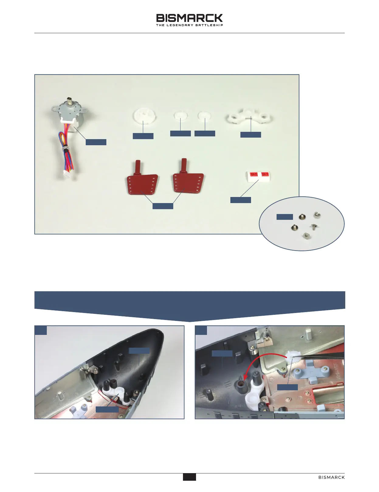
01. ASSEMBLING THE RUDDERS AND COGS
01 02
12302
PWM
12303 12304
12305
12301
12306
12307
12303
12305
11801
11801
1
2
3
STAGE 123
THE TWIN RUDDERS
COMPONENTS CHECKLIST
Fit the port cog 123-03 (marked L) on the raised socket
on the port side of the stern 118-01, as indicated. Note
the position of the three ribs: rib 1 (on the inside of the
hull) sits between the ribs 2 and 3 on the cog.
Position the cog support 123-05 on the hull assembly
so that it sits on the raised screw sockets in the stern
section 118-01.
123-01: Motor for the rudders
123-02: Large cog
123-03: Port cog (L)
123-04: Starboard cog (R)
123-05: Cog support
123-06: Two rudders
123-07: Cable label (D1)
PWM: Five 2 x 4mm PWM
screws
27
27
AGORAMODELS BISMARCK
PB
AGORAMODELS BISMARCK
 Loading...