03
05
07
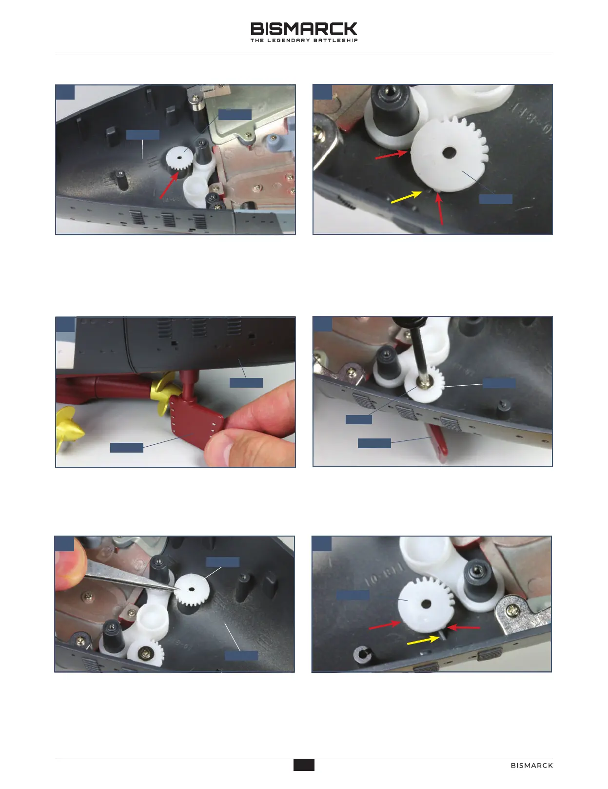
This detail shows the port cog 123-03 viewed from the
port side. Turn the cog so that the ribs on the cog (red
arrows) are positioned as shown, with one against the
rib on the inside of the hull (yellow arrow).
11801
12303
12306
11801
12306
12303
12304
12303
11801
PWM
12304
04
06
08
This shows cog 123-03 correctly positioned in the port
side of the stern 118-01: note that the teeth point
towards the centre of the hull, as indicated.
Insert the shaft of the first rudder 123-06 up into
the hole on the port side of stern section 118-01,
as shown.
The shaped end of the shaft of the rudder fits into a
corresponding recess in the cog. Fix the rudder 123-06
in place using a PWM screw, inserted through the cog
and the raised socket and into the rudder shaft.
Fit the starboard cog 123-04 (marked R) on the raised
socket on the starboard side of the stern section
118-01. Make sure the ribs are aligned correctly, so that
the rib on the inside of the hull is between the ribs on
the cog.
Ensure that the ribs of cog 123-04 are in the correct
position and the teeth are facing towards the centre
of the hull. Note that with the cogs 123-04 and 123-03
in the correct positions, the rudders are parallel.
28
28
AGORAMODELS BISMARCK
29
AGORAMODELS BISMARCK
 Loading...