09
Completed work
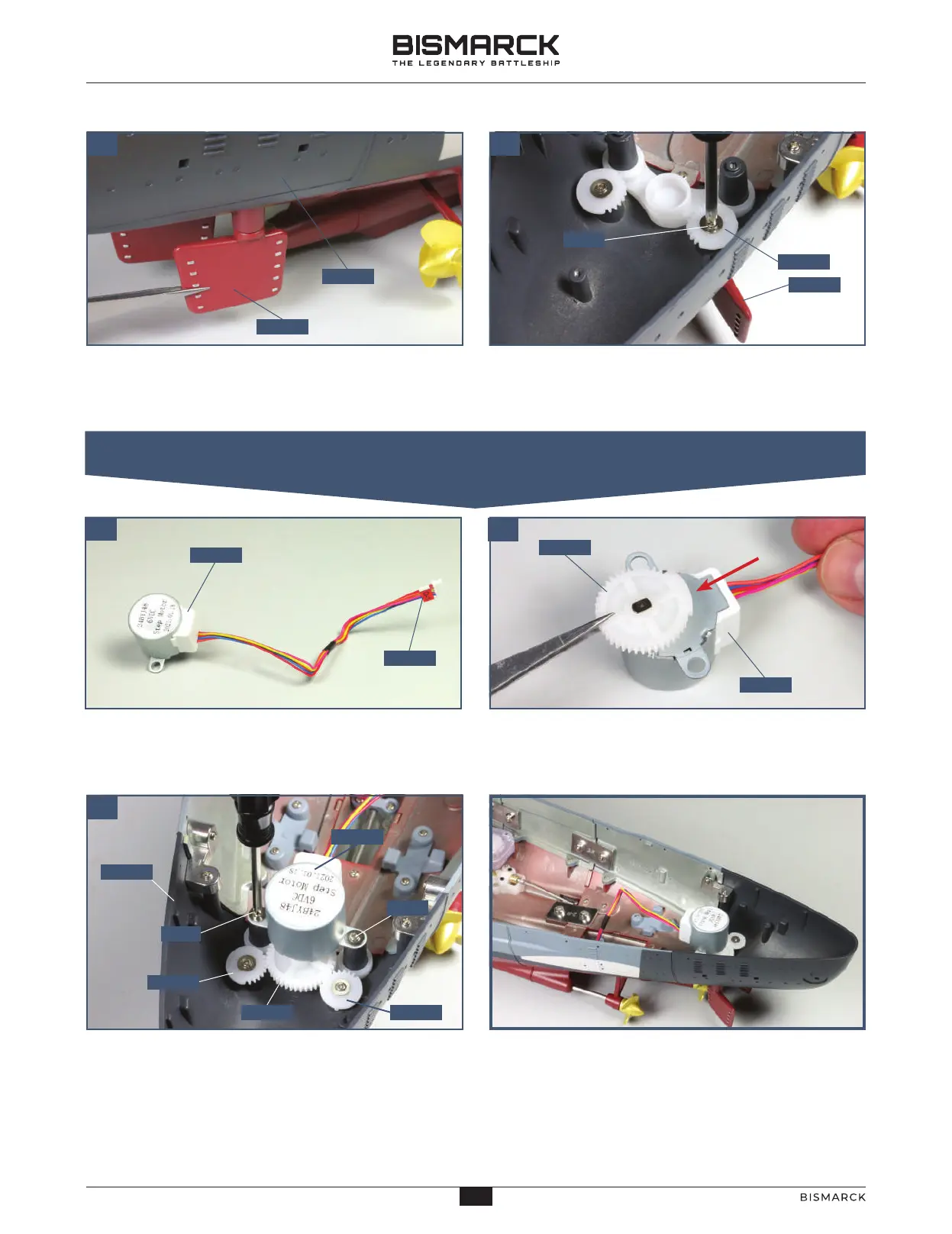
The two rudders and the motor have been
fitted to the stern of the model.
You may find that the fit of the motor is a bit wobbly.
This will be fixed in a later stage.
Fit the shaft of the second rudder 123-06 up into the
hole in the stern section 118-01 on the starboard side.
02
Fix the rudder 123-06 in place using a PWM screw,
inserted through the cog and the raised screw socket
and into the rudder shaft.
Wrap the cable label 123-07 (D1) round
the end of the cable from motor 123-01
near to the connector, as shown.
Fit the large cog 123-02 on the shaft of the
motor 123-01. Make sure the side without
any teeth is positioned as shown (arrow).
Ensure that the cogs 123-03 and 123-04 are positioned
as shown, with the rudders parallel. Identify the fixing
point for the motor 123-01 at the rear of part 118-01. Fix
the motor in place with two PWM screws so that the
teeth of cog 123-02 interlock with the cogs 123-03 and
123-04.
02. FITTING THE MOTOR FOR THE RUDDER
01
03
12306
11801
12306
12304
12301
12307
12301
12303
PWM
12301
12302
12302 12304
11801
10
PWM
PWM
29
28
AGORAMODELS BISMARCK
29
AGORAMODELS BISMARCK
 Loading...