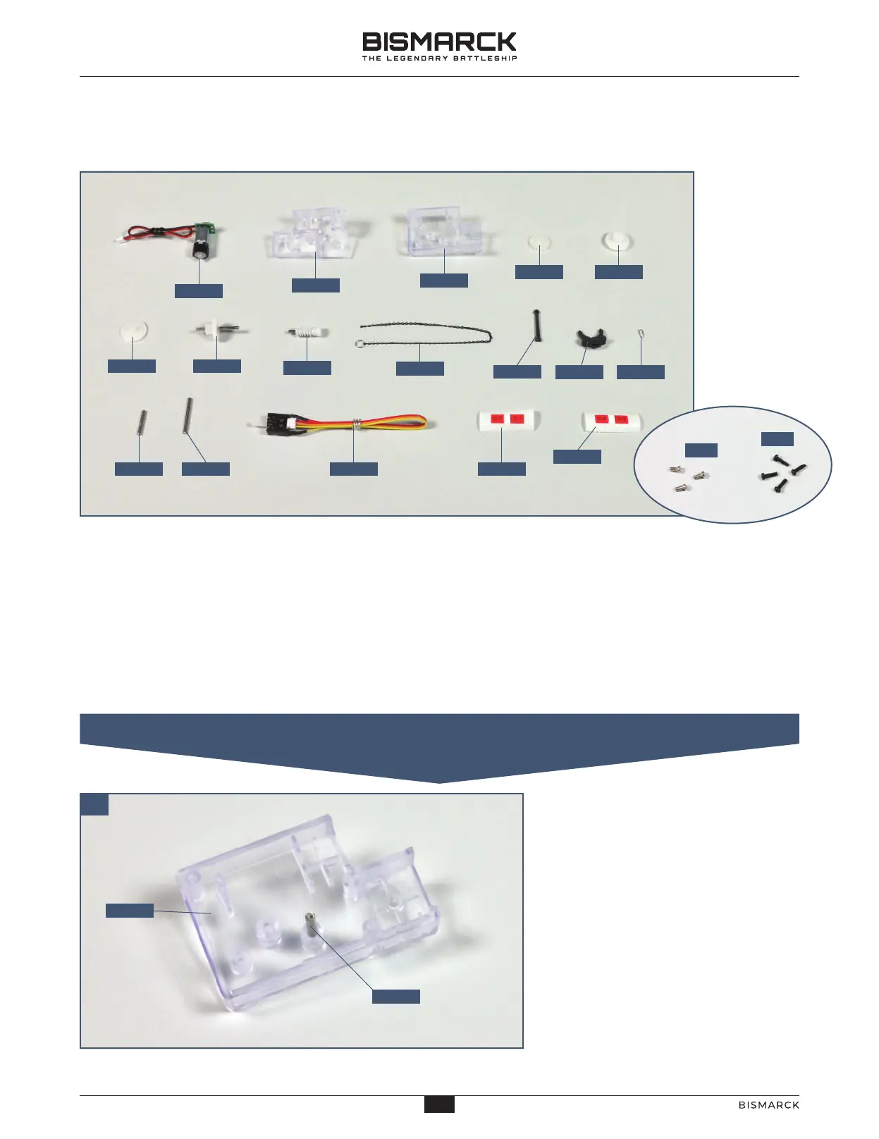
01. ASSEMBLING THE GEARBOX FOR THE AFT ANCHOR
01
12401
PM
PB
12402
12403
12404
12405
12406
12407
12408
12409
12410
12411 12412
12413 12414 12415 12416
12417
12403
12413
STAGE 124
THE AFT ANCHOR AND MOTOR
COMPONENTS CHECKLIST
124-01: Anchor motor
124-02: Gear housing (left side)
124-03: Gear housing (right side)
124-04: Cog with brake tab
124-05: Cog with cable reel
124-06: Cable reel
124-07: Cog on shaft
124-08: Worm gear on shaft
124-09: Anchor chain
124-10: Anchor shank
124-11: Anchor head
124-12: Anchor ring
124-13: Shaft (shorter)
124-14: Shaft (longer)
124-15: Switch and cable
124-16: Cable label (D-7)
124-17: Cable label (D-8)
PM: Three 2 x 4mm PM screws
PB: Four 1.7 x 6mm PB screws
Place the right-hand side of the gear
housing 124-03 on your worktop.
Insert the shorter shaft 124-13 into
the socket in the housing, as shown.
30
30
AGORAMODELS BISMARCK
PB
AGORAMODELS BISMARCK
 Loading...