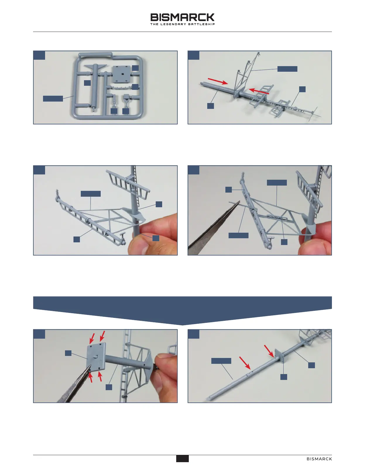
In close-up, frame 125-02 includes the middle mast
section E, a platform F, a rail G, the signal lamp
support H and the signal lamp I.
01 02
Platform F fits on the lower end of the mast section E.
Make sure you fit the platform the right way round – the
sides have holes close to the edges (arrows). The wider
side of the platform (on the left in this photo) is beneath
the spar support 125-11. Glue the platform in place.
The peg on the lower end of mast section E, which
pokes through the hole in the platform F, fits into
the top of the mainmast section 125-01. Check
that they are correctly orientated, noting the position
of the holes (arrows). Glue the parts together, as shown.
11 12
The spar support 125-11 slopes upwards at an angle to
the mast. The spar A from frame 125-03 is fitted to
the brackets on the front of part 125-11. Glue the spar
in place, as shown.
Glue the rail G from frame 125-02 to the central
strut of part 125-11, on the upper side, as shown.
The antenna 125-12 is glued in place on the leading
edge of the spar A, as shown.
Take the mast section E from frame 125-02. Fit mast
sections B and E together with the spar support
125-11 between them. Holes in parts B and E are
facing downwards. Glue part E in place on part B.
09 10
12512
12502
12511
12511
12501
E
F
H
G
I
B
E
E
B
A
12511
G
A
E
F
F
E
02. THE LOWER SECTION OF THE MAINMAST
37
36
AGORAMODELS BISMARCK
37
AGORAMODELS BISMARCK
 Loading...