26 27
aidacare.com.au
7.4 SELF HELP POLE AND IV POLE ASSEMBLY
The Self Help Pole (SHP) provides an overhead patient support or manoeuvring
handle to assist with repositioning. The IV Pole provides a telescoping height
adjustable hanger for tubes, bags and other equipment.
The FL250 Self Help Pole and FL250 IV Pole are designed to attach to the FL250 Head
Board and therefore will move with any Head Board movement – up, down, tilt etc.
WARNING
Be aware of encumbrances such as walls, cupboards, curtains,
lights etc when manoeuvring the bed with a Self Help Pole or IV
Pole attached. Pay particular attention when tilting the bed or
using the Trendelenburg or reverse Trendelenburg functions.
Carton Contents:
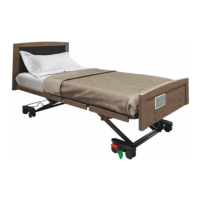
FL250 Self Help Pole:
• 1 x Self Help Pole in 2 sections, top and base
(8 x joining bolts mounted to top section)
• 1 x Handle with Strap
• 1 x SHP attachment and receiver bracket
FL250 IV Pole:
• 1 x Telescoping IV Pole
• 1 x IV Pole attachment and receiver bracket
Self Help Pole IV Pole
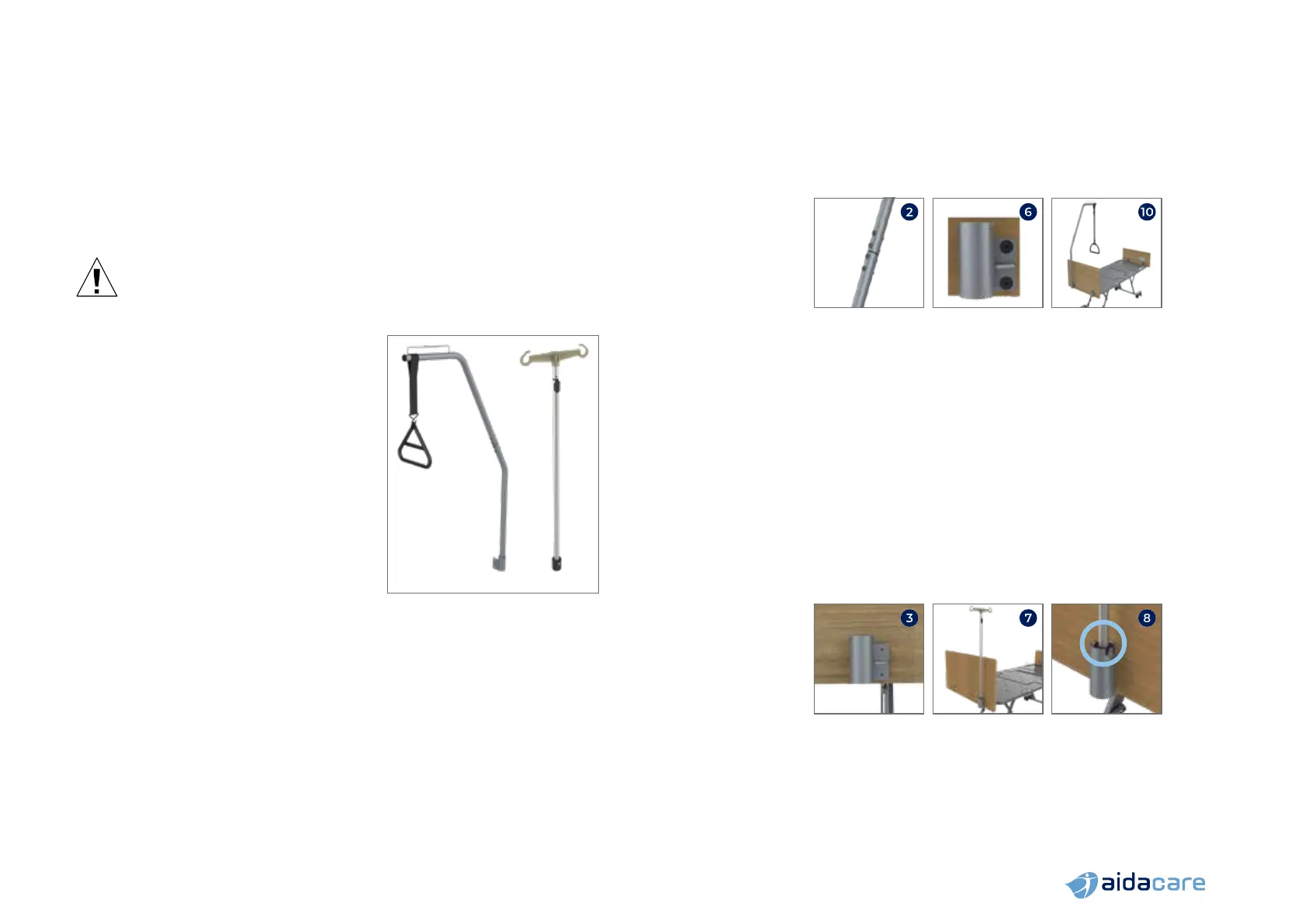
Assembly of the FL250 Self Help Pole
1. Remove 8 bolts from top section
2. Join top section with base section, insert and fasten all 8 bolts firmly
3. Remove the Head Board from the bed
4. Choose which side of the Head Board to mount the SHP on – left or right
5. Undo the left or right Head Board attachment bracket screws and remove
the outside plate
6. Position the SHP attachment and receiver bracket over the Head Board holes
and attach using Head Board Attachment Bracket screws just removed
7. Fasten until very firm. This also re-affixes the Head Board attachment bracket
8. Reinstall the Head Board back onto the bed
9. Insert base of SHP into the receiver and position so the peg on the SHP sits
in the slot of the receiver
10. SHP will now sit securely in place
11. SHP position can be altered by lifting and twisting to the second notch position
Assembly of the FL250 IV Pole
1. Choose which side of the Head Board to mount the IV Pole on – left or right
2. Undo the left or right Head Board attachment bracket screws and remove
the outside plate
3. Position the IV Pole attachment and receiver bracket over the head board
holes and attach using Head Board Attachment Bracket screws just removed
4. Fasten until very firm. This also re-affixes the Head Board attachment bracket
5. Reinstall the Head Board back onto the bed
6. Insert base of IV Pole into the receiver and position so the peg on the IV Pole
sits in the slot of the receiver
7. IV Pole will now sit securely in place
8. IV Pole position can be altered by lifting and twisting to the second notch position
9. IV Pole height can be adjusted via the telescoping shaft