Page 29
14 Remote Operation
The 1908P model can be remotely controlled via its RS232, USB, GPIB or LAN interfaces. The
1908 (non ‘P’) can only be controlled via USB. In order to remotely control the instrument via
RS232, GPIB or LAN, mains power must be applied. USB however can function with or without
mains power applied as it is host powered. As such the USB interface can be used when powered
from the batteries.
The GPIB interface provides full facilities as described in IEEE Std. 488 parts 1 and 2.
The RS232 interface communicates directly with a standard COM port.
The USB interface enumerates as a Communications Class device and interacts with application
software through a standard virtual COM port device driver on the PC. The instrument firmware can
be updated in the field via the USB port; see the ‘Maintenance’ section for details.
The LAN interface is designed to meet LXI (Lan eXtensions for Instrumentation) version
1.4 LXI Core 2011. Remote control using the LAN interface is possible using the TCP/IP Sockets
protocol. The instrument also contains a basic Web server which provides information on the unit
and allows it to be configured from a web browser. Simple command line control from the browser
is also possible.
14.1 GPIB Interface
The standard GPIB interface 24-way connector is located on the instrument rear panel. The pin
connections are as specified in IEEE Std. 488.1-1987 and the instrument complies with both IEEE
Std. 488.1-1987 and IEEE Std. 488.2-1987.
It provides full talker, listener, service request, serial poll and parallel poll capabilities. There are no
device trigger or controller capabilities. The IEEE Std.488.1 interface subsets provided are:
SH1, AH1, T6, L4, SR1, RL2, PP1, DC1, DT0, C0, E2.
The GPIB address of the unit is set from the front panel: select the {Utilities} menu then {Addr}.
The present GPIB address is displayed. If it needs to be changed, use the Navigator keys to set the
desired address and then press [OK].
The interface will operate with any commercial GPIB interface card, using the device drivers and
support software provided by the manufacturer of that card.
14.2
RS232 Interface
The 9-way D-type serial interface connector is located on the instrument rear panel. It should be
connected to a standard PC port preferably using a fully wired 9-way 1:1 male-female cable without
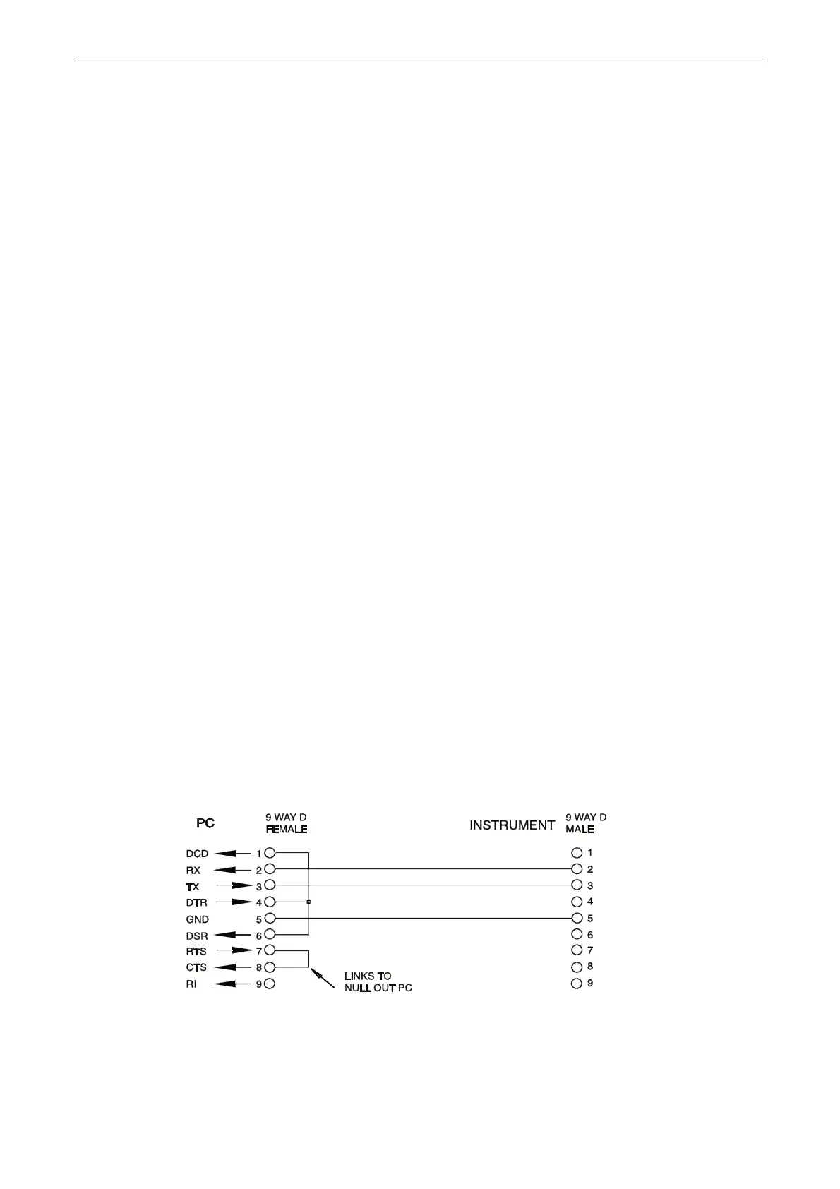
any cross-over connections. Alternatively, a 3-way cable can be used, connecting only pins 2, 3
and 5 to the PC, but with links made in the connector at the PC end between pins 1, 4 and 6 and
between pins 7 and 8, as shown in the diagram:
Most commercial cables provide these connections.
In addition to the transmit and receive data lines, the instrument passively asserts pins 1 (DCD) and
6 (DSR), actively drives pin 8 (CTS) and monitors pin 4 (DTR) from the PC. This allows the use of a
fully wired 9-way cable.