Do you have a question about the AINSWORTH A640 and is the answer not in the manual?
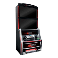
Details the main cabinet structure, doors, and locking mechanisms.
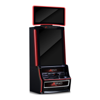
Explains the combined monitor door and 40-inch LCD assembly.
Details the buttons and functions for adjusting monitor settings.
Identifies components housed within the main door assembly, including bill acceptor and speakers.
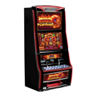
Explains the belly panel door, its artwork, and LED lighting.
Provides an overview of the terminal's internal components like logic cage and power supply.
Details the note validator, its function, and locking mechanisms.
Describes the note stacker for storing accepted notes and its door mechanism.
Details the optional ticket printer and its paper dispensing slot.
Explains the logic cage housing the mainboard and its security latch.
Specifies the physical dimensions of the A640 wagering terminal.
Details pre-installation inspection steps for exterior and interior components.
Provides guidance on mounting the wagering terminal to a base or console.
Outlines the step-by-step procedure for installing the wagering terminal.
Explains how to use System Tests Mode for hardware assessment and audits.
Details the procedure for testing the bill acceptor's note recognition and operation.
Describes the basic test to determine if the printer is acknowledged by the software.
Explains how to calibrate the terminal's touchscreen for accuracy.
Details how to test door interlocks using the switches tab on the diagnostic screen.
Allows validation of software and BIOS SHA-1 against jurisdictional approval certification.
Provides information for routine servicing, including cleaning of various components.
Provides specific steps to clear jams within the note validator unit.
Details the procedure for safely resetting the terminal's circuit breaker.
Details the steps required to open the monitor door assembly.
Explains how to fine-tune and adjust the monitor using its control board.
Provides the procedure for removing and installing the 40-inch LCD monitor assembly.
Details the procedure for removing and installing the main door speakers.
Explains the process for removing and installing the subwoofer unit.
Details the procedure for opening and closing the main door assembly.
Procedure for removing and installing the LCD touchscreen with bash button panel.
Details how to change the LED light panel within the belly door.
Provides instructions for removing and installing the note validator unit.
Explains the process for removing and installing the note validator housing.
Details the procedure for removing and installing the MEI frame for the note validator.
Explains how to remove and install the optional ticket printer.
Details the procedure for removing a blank and installing a player tracking module.
Provides instructions for replacing the integrated universal power supply unit.
Describes the optional fiber optic interface module and its status LEDs.
Details the procedure for removing and installing the mainboard within the logic cage.
Explains the careful procedure for removing and replacing the backplane board.
Procedure for removing and installing the logic cage and backplane board assembly.
Details the RAM Clear process for major faults or base/game type changes.
Instructions for performing a base change on the wagering terminal.
Lists error and status messages, their causes, and recommended remedies.
Lists common terminal problems, possible causes, and suggested remedies.
Lists possible causes of errors indicated by the note validator's LED display.
Provides a list of part descriptions and their corresponding part numbers.
| Category | Arcade Game Machines |
|---|---|
| Manufacturer | AINSWORTH |
| Model | A640 |
| Buttons | 6 |
| Joystick | Yes |
| Power Supply | Standard arcade power supply |
| Dimensions | Varies by cabinet type |