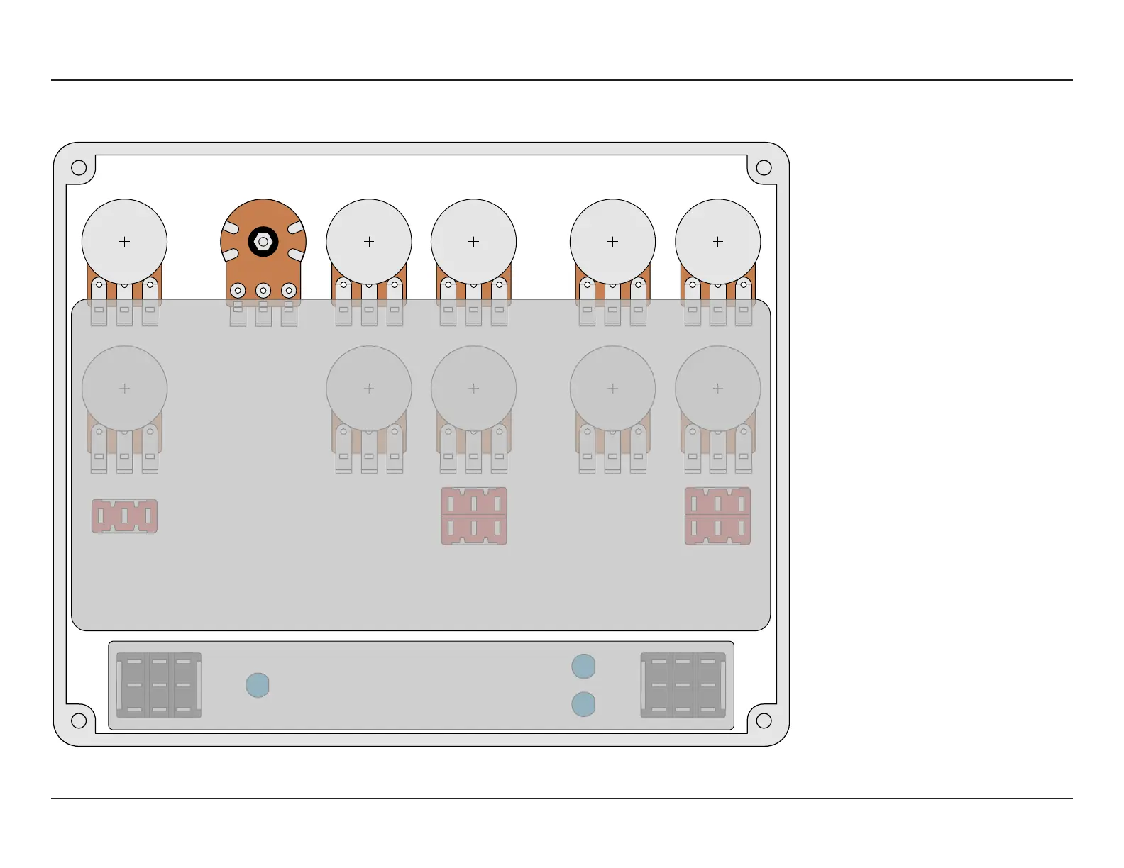
ENCLOSURE LAYOUT
Enclosure is shown without jacks. See next page for jack layout and wiring.
L4 PREAMP 18
1590XX
Note: The upper pads for the dual-gang
gain potentiometer appear to be cut
in half. This is intentional! It’s called a
plated half-hole or castellated via, and it’s
used so that the PCB can lay flat across
the pots instead of angling upward for
the dual pot.
Solder it like you would if they were
normal pads, but bend the upper set
of pins forward slightly so they make
contact with the inside of the pads.
 Loading...