- 5 -
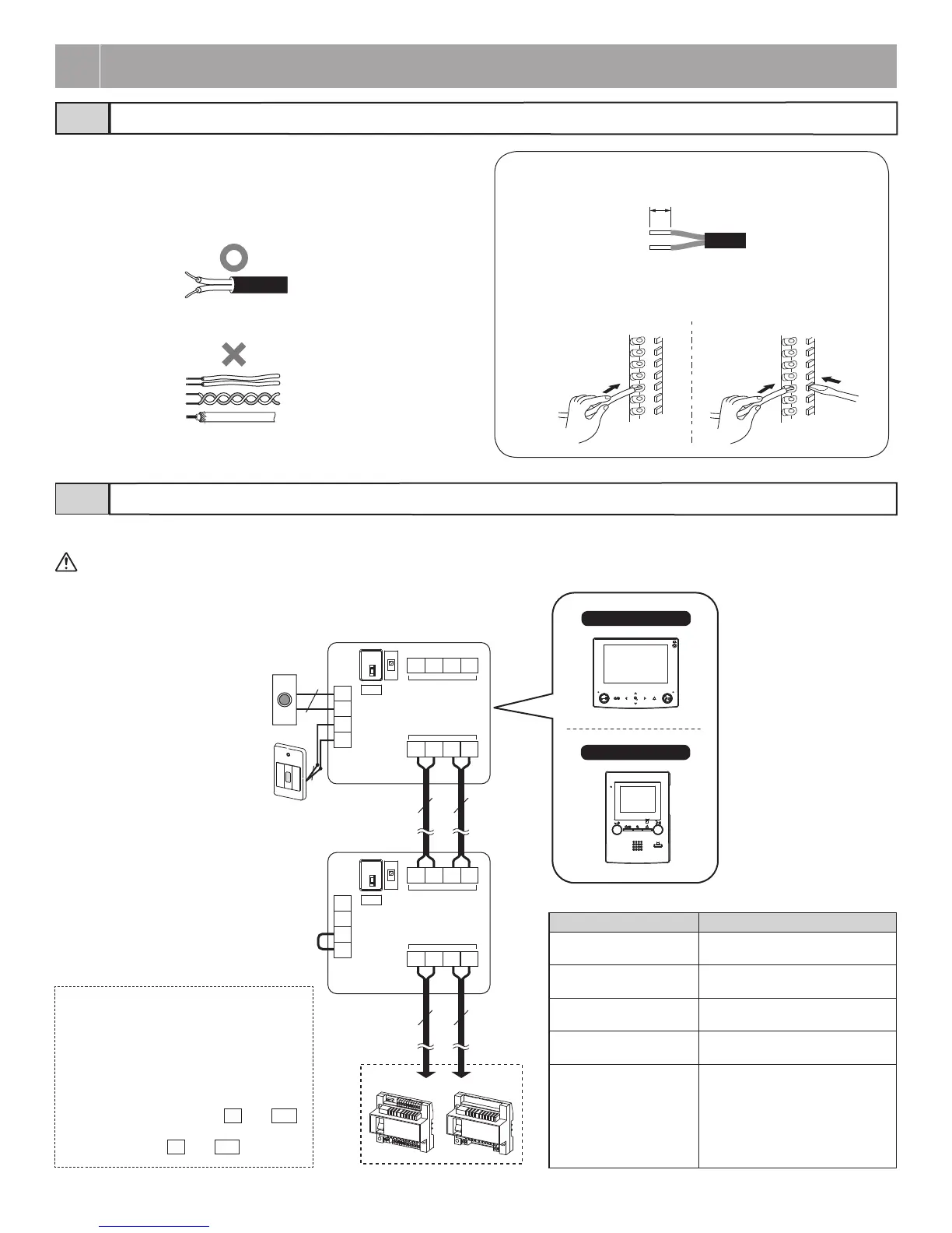
Appropriate cable3-1
• Use PE (polyethylene)-insulated PVC jacket cable.
Parallel or jacketed 2-conductor, mid-capacitance non-shielded cable
is recommended.
• Never use individual conductors, twisted pair cable or coaxial cable.
1
2
Weak electrical current line connection
Insert the wire into the direct terminal. If it is difficult to insert the
wire, insert it while pressing the release button.
(x2)
3
WIRING
8mm (3/8")
Standard system for residence/tenant (Loop Wiring method)3-2
GT-VBC GT-BC
C
CE
K
KE
IN
OUT
B1
B2
R1
R2
B1
B2
R1
R2
C
CE
K
KE
IN
OUT
B1
B2
R1
R2
B1
B2
R1
R2
NP
NP
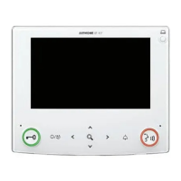
GT-1C7-L/GT-1C7
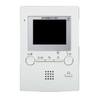
GT-1M3-L/GT-1M3
B
A
SW1
B
A
SW1
1P
NP
1P
NP
1P
NP
1P
NP
Terminal setting:
For terminating a residential/tenant
station, turn SW1 to the [A] side.
Emergency
alarm switch
(*2)
Doorbell
(*1)
* Refer to the GT SYSTEM Installation manual (page 27) when connecting the stations by using the 4-way video junction unit (GT-4Z).
To prevent shorts, unused cables should be insulated.
(*1): Doorbell
• N/O contact (non-locked type)
• DC 12 V/0.1 A or higher
(*2): Emergency alarm switch
• N/C contact (locked type)
• DC 12 V/0.1 A or higher
(*3): Jumper wiring between
K
and
KE
.
Do not remove the jumper wire when
not using the
K
and
KE
terminals.
(*3)
Capacity of residential/tenant stations
System Capacity
Total residential/tenant
stations [Standard system]
Max. 48
Total residential/tenant
stations [Expanded system]
Max. 500
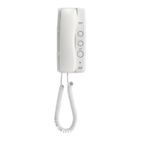
Residential/tenant stations
[Standard system]
Max. 25 (per trunk of GT-BC)
Residential/tenant stations
[Expanded system]
Max. 125 per sub trunk line (max.
25 per trunk of terminating GT-BC)
Residential/tenant stations
in the same residence
Max. 4 under the following
conditions:
• GT-1C7(-L) × Max. 1
(with GT-1A (or GT-1D) × Max. 3)
• GT-1M3(-L) × Max. 2
(with GT-1A (or GT-1D) × Max. 2)
 Loading...