-6-
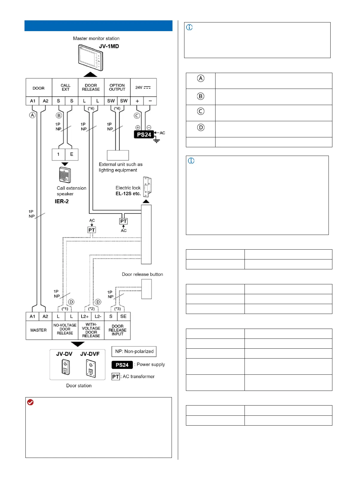
Wiring diagram and specifications
ATTENTION
Do not use the unused terminals for other purposes.
The wiring between each device should not be in the
same wiring jacket.
Insulate and secure unused low-voltage lines.
Only connect an electric lock to a single location.
The external door release button activates only electric
lock which is connected to door station.
Be sure to ground the power supply.
NOTE
The sequence of terminals in the diagram may differ from
the actual product.
Also refer to the instructions for each device to be
connected.
PE Φ0.65 mm (22 AWG): 50 m (165')
PE Φ0.8-1.2 mm (20-16 AWG): 100 m (330')
PE Φ0.65 mm (22 AWG): 50 m (165')
PE Φ0.8-1.2 mm (20-16 AWG): 150 m (490')
PE Φ0.65 mm (22 AWG): 5 m (16'5")
PE Φ0.8 mm (20 AWG): 10 m (33')
PE Φ0.65 mm (22 AWG): 15 m (49')
PE Φ0.8-1.2 mm (20-16 AWG): 30 m (98'5")
PE Φ0.65-1.2 mm (22-16 AWG)
NOTE
The wiring distance between the master monitor station
and the power supply can be extended up to 25 m (82')
by using a PE Φ1.2 mm (16 AWG) cable. However, the
maximum distance between the door station and the
master monitor station will be shortened to 70 m (230')
by using a PE Φ0.8-1.2 mm (20-16 AWG) cable.
When the wet contact output from the door station is 12
VDC, 580 mA (higher than 500 mA, 580 mA or lower),
the wiring distance between the door station and the
master monitor station should be 70 m (230') or shorter
by using a PE Φ0.8-1.2 mm (20-16 AWG) cable.
(*1): Output specifications
24 VDC, 1 A (resistive load)
(*2): Output specifications
(*3): Input specifications
Terminal short-circuit
current
Voltage between
terminals
5 VDC or less (between open
terminals)
(*4): Output specifications
24 VDC, 1 A (resistive load)