– 8 –
5
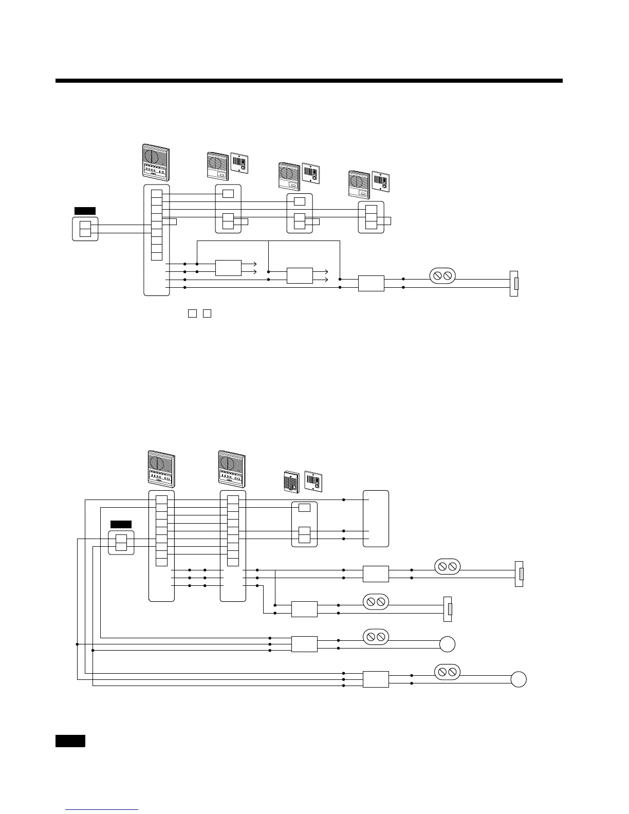
Wiring Diagrams - Applications
One master station + three door stations using 2-conductor method with door release
Two master stations + two sub stations with full communication between all stations, external
signaling, and door release
PS12
PS-1225/S/UL, PS-1215DIN
-
+
3
2
1
LEF-3L
*Keep E /
-
jumpers only for 2-conductor method, remove when installing with 3-conductor method
E
-
C
Y
RY-PA
RY-PA
for door 1
Black
+
R
White
Red
Brown
Orange
1
-
1
E
-
1
E
-
for door 2
for door 3
AC Transformer
Door strike
Black
Black
Yellow
E
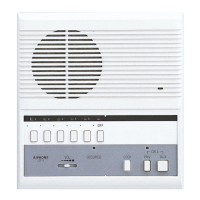
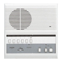
LE Series sub / door station
LE-A/LE-DA etc
LE Series sub / door station
LE-A/LE-DA etc
LE Series sub / door station
LE-A/LE-DA etc
RY-PA
PS12
* * *
*
-
+
C
2
1
3
-
E
R
Y
+
Yellow
LEF-3L LEF-3L
“M3” “M3”
for door 1
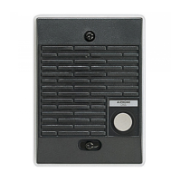
LE-SS/A Series
door station
3
2
1
C
-
E
R
Y
+
1
-
E
Red
Blue
Black
RY-PA
RY-PA
for door 2
AC Transformer
RY-AC/A
RY-AC/A
for door 2
Bell
for door 1
AC Transformer
Power source
for strobe
Power source
for bell
Strobe
YellowBlack
Yellow
Yellow
Black
White
Black
Red
White
Black
Red
Door strike
Door strike
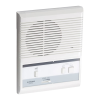
LE-D/LE-DA
PS12
White
Red
Brown
Orange
White
Red
Brown
Orange