– 2 – – 3 –
3
Mounting
Front Case
Single-gang box
83.5mm,
3-5/16"
Screw (2)
Wall
Lift and pull off
Chassis
Loosen
Push either side
Operation
Plate
83.5mm,
(3-5/16")
Single-gang box
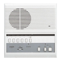
LE-D Unit
Connector
2-gang box
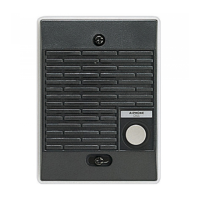
Stainless
Cover
Screw (2)
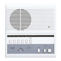
Main Unit
83.5mm,
(3-5/16")
For surface wall cable run, pass through
opening on top or bottom of back case.
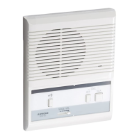
LEM-1DL LE-D
LE-DA
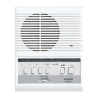
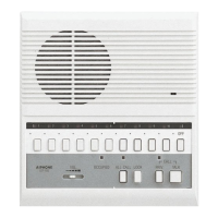
Back wiring LE subs
4
Wiring
+
1
–
E
EL
EL
R
for AC or DC power supply
for calling & communication
for communication (common)
for door release & its power supply
Normally open dry contact closure
+
–
1
E
EL, EL
}
PT-1210N
NP
NP
NP
PT-1210N
LE-DA
DOOR RELEASE
EL-12S
(AC 12V, 125mA)
LEM-1DL
1
E
–
1
E
+
–
EL
EL
AC Transformer
PT-1210N
NP
NP
PT-1210N
LE-DA
DOOR RELEASE
(Max. AC 30V, 1A
Max. DC 30V, 1A)
LEM-1DL
1
E
–
1
E
+
–
EL
EL
Use a suitable power source
locally available.
When EL-12S door release is used;
When door release of OTHER manufacturer is used;
The actual terminal locations are
different from the ones shown in
the diagram below.
NP: Non-polarized
Run separately each cable to
Door station and Door Release.