Do you have a question about the Air-Con 18000 BTU and is the answer not in the manual?
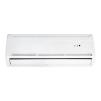
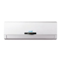
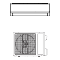
Details the appearance and specifications of various indoor unit models.
Outlines the outdoor unit models and their respective BTU capacities.
Lists essential safety instructions to prevent injury and damage during the installation process.
Highlights critical warnings regarding electrical hazards, grounding, and correct wiring practices.
Provides specific installation parameters, including recommended torque values for pipe connections.
Diagram showing the refrigerant path during the cooling operation of the unit.
Diagram illustrating the refrigerant flow for heat pump operation, including the reversing valve.
Detailed circuit diagrams illustrating the electrical layout and connections of the indoor unit.
Electrical schematics detailing the components and connections within the outdoor unit.
Schematic for the 38-section crystal color ordinary PCB, showing its electronic components.
Schematic diagram for the 65 Mitsubishi model featuring the main control chip.
Schematic diagrams for the 85-section PCBs, illustrating their electronic configurations.
Detailed schematics for the 18NV 85 model, covering electrically controlled functions.
Schematic for the Mitsubishi Jin Dynasty 85 model's electrically controlled motherboard.
Describes the function and status indication of the two-LED display panel.
Explains the indicators for the eleven-LED display, including operational status.
Details the functions of display panels featuring two LEDs and an 8-segment LED display.
Outlines the operational modes and indicators for the multi-color LED display panel.
Explains the system's method for detecting frost and initiating the defrost cycle.
Outlines the specific conditions and timing managed by the outdoor PCB for defrosting.
Defines the sensor conditions that initiate and terminate the defrost cycle.
Procedures for identifying and rectifying faults related to indoor room and coil sensors.
Steps to troubleshoot indoor sensor issues, including resistance checks and PCB verification.
| Brand | Air-Con |
|---|---|
| Model | 18000 BTU |
| Category | Air Conditioner |
| Language | English |