Do you have a question about the Air-Con 24000 BTU and is the answer not in the manual?
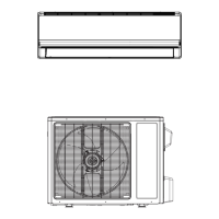
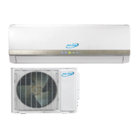
Visual overview of different indoor unit models.
Visual overview of different outdoor unit capacities.
Detailed breakdown of the air conditioner model number coding system.
Critical safety instructions to prevent injury and property damage during installation.
Key warnings and cautions regarding electrical safety and installation hazards.
Guidelines for safe and effective operation of the air conditioner.
Specific details and requirements for installing the air conditioner unit.
Torque values for installation connections based on pipe diameter for secure fitting.
Guide to selecting the correct power cord gauge based on unit capacity requirements.
Specifications for maximum allowable pipe length and elevation difference for optimal performance.
Illustrates the refrigerant path during cooling mode operation.
Illustrates the refrigerant path during heat pump (heating) mode operation.
Circuit diagrams detailing indoor unit electrical components and connections.
Circuit diagrams detailing outdoor unit electrical components and connections.
Schematic for the 38-section crystal color ordinary PCB.
Schematic for the 65 Mitsubishi main chip control board.
Schematic diagrams for various 85-section model control boards.
Schematics for compatible electrically controlled 18NV 85 models.
Schematics for the Mitsubishi Jin Dynasty 85 model control board.
Describes different types of display panels and their LED indicators.
Details the functions of LEDs and displays on various panel types.
Explains control logic for compressor and fans based on temperatures during cooling.
Describes the automatic defrosting process based on sensor readings.
Details defrost management by the outdoor PCB based on specific conditions.
Conditions for starting and ending defrost based on outdoor sensor data.
Explains the dehumidification process and its operational cycle.
Describes the operation of the unit in ventilation mode.
Details conditions for entering and operating in automatic mode.
Explains timer, sleep, and emergency key functions for user control.
Details the failure code system and how to interpret LED indications.
Explains fault codes E2, E3, E4 for sensor errors and unit abnormalities.
Explains fault codes E5, E6, E7 for motor issues and feedback faults.
Explains fault code E8 for frost protection or overheating issues.
Steps to diagnose and resolve errors related to indoor temperature sensors.
Troubleshooting guide for issues where the indoor fan motor fails to operate.
Troubleshooting guide for issues where the compressor fails to start or operate.
Addresses interference from sunlight and thyristor lights on the receiver.
Troubleshooting steps for remote control failures, battery issues, and transmission problems.
Verifies power supply, unit display, and basic operational status.
Checks for proper operation of key components and the control PCB.
Verifies power supply, wiring, and insulation for overall unit startup.
Checks fuses, transformer output, and PCB voltages for unit startup.
| Brand | Air-Con |
|---|---|
| Model | 24000 BTU |
| Category | Air Conditioner |
| Language | English |