4
IMAT PT- E
Before installing the actuator in aggressive environment,
ensure that the selected protection level is suitable.
• Actuator designation and marking (see technical data
sheets):
The actuator type, size, operating pressure, output torque,
direction of rotation, spring action, operating temperature
and type of connections/interfaces are determined by
designation.
• All POWER TECHNOLOGY actuators are supplied with
an identification l abel s howing t he s erial n umber a nd a ll
necessary information on use, service, operation and prod-
uct designation. Where applicable, the label indicates the
classification according to ATEX Directive 2014/34/EU.
4) OPERATING FUNCTION AND DIRECTION OF ROTATION
The actuator is a pneumatic device for remote opera-
tion of industrial valves. The operation (90°,120°,135° or
180° rotation) may be activated by different methods:
• Direct mounting of solenoid valve (5/2 for double acting,
3/2 for spring return) to pressure connections 2 and 4,
connected to supply and control lines
• Screwed connection (to pressure connections 2 and 4)
with air lines from separate control cabinet.
The standard rotation (when port 4 is pressurized or for
spring action) is clockwise to close. When port 2 is pres-
surized, counter-clockwise rotation is obtained.
POWER TECHNOLOGY actuators can be supplied with
different types of assembly/rotation direction depending
on the type of required operation and/or installation, see
technical data sheets.
5) ACTUATOR INSTALLATION INSTRUCTIONS
The POWER TECHNOLOGY actuator is a pneumatic device
for the remote operation of industrial valves. The actuator will
operate through 90°,120°,135° and 180° rotation permitting
the opening and closing of many types of valves up to 180°
rotation. All the necessary technical information to install the
actuator correctly and safely onto a valve i.e.:
Dimensions, Output torque, Supply pressure, Air volume,
Stroke adjustment, Operating time, Operating tempera-
ture, Direction of rotation and Weight is stated clearly on the
Actuator label, in the catalogue and technical data sheets.
Please read all technical information before proceeding with
the actuator installation.
5.1) Important Safety Notice!
• For safety reasons, the actuator must not be pressurized
at any time during installation as injury may result.
• The utmost cleanliness is required during air supply con-
nection to the actuator i.e. the connecting pipe thread,
fittings and seals must be clean and dirt-free.
• When fitting accessories onto the actuators, assemble
them in such a way that the emergency control of the
solenoid valve and the top of the drive shaft are eas-
ily accessible, should emergency manual operations be
required.
• Before fitting onto the valve, make sure that the actua-
tor/valve are correctly orientated, depending upon which
direction of rotation is required.
GB
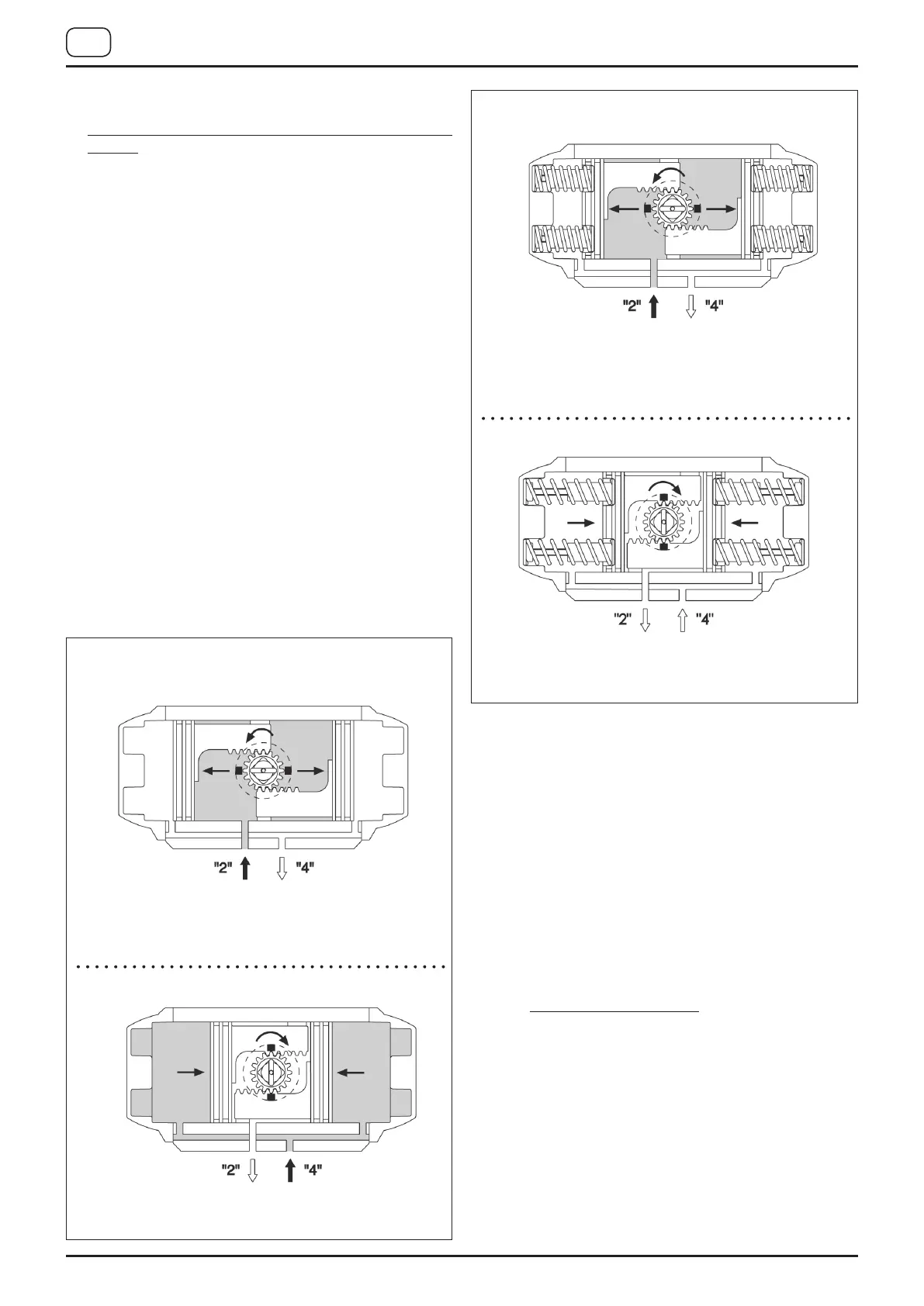
Air supplied to port 2 forces the pistons towards the actuator
end caps. A counter-clockwise rotation is achieved.
Exhaust air exits from Port 4.
Air supplied to Port 4 forces the pistons inward.
A clockwise rotation is achieved. Exhaust air exits from Port 2.
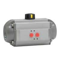
DOUBLE ACTING OPERATION FUNCTION
(STANDARD ROTATION TYPE “ST”) TOP VIEW
SINGLE ACTING OPERATION FUNCTION
(STANDARD ROTATION TYPE “ST”) TOP VIEW
Air supplied to Port “2” forces the pistons toward the actuator
end caps, compressing the springs.
A counter-clockwise rotation is achieved. Exhaust air exits
from Port 4.
The loss of air pressure (air or electric failure) at Port “2” allows
the springs to force the pistons inward.
A clockwise rotation is achieved.
Exhaust air exits from Port 2.
 Loading...