5
GB
IMAT PT- E
• For spring return actuators, avoid that dangerous and/
or corrosive substances in the working environment en-
ter into the external chambers by using adequate filters
and/or solenoid valves.
• Remove plugs from actuator air connections during in-
stallation and operation. Protect the air connections of
actuators not being used immediately.
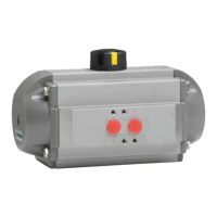
5.2) Interfaces for actuator controls and connections, Fig. A:
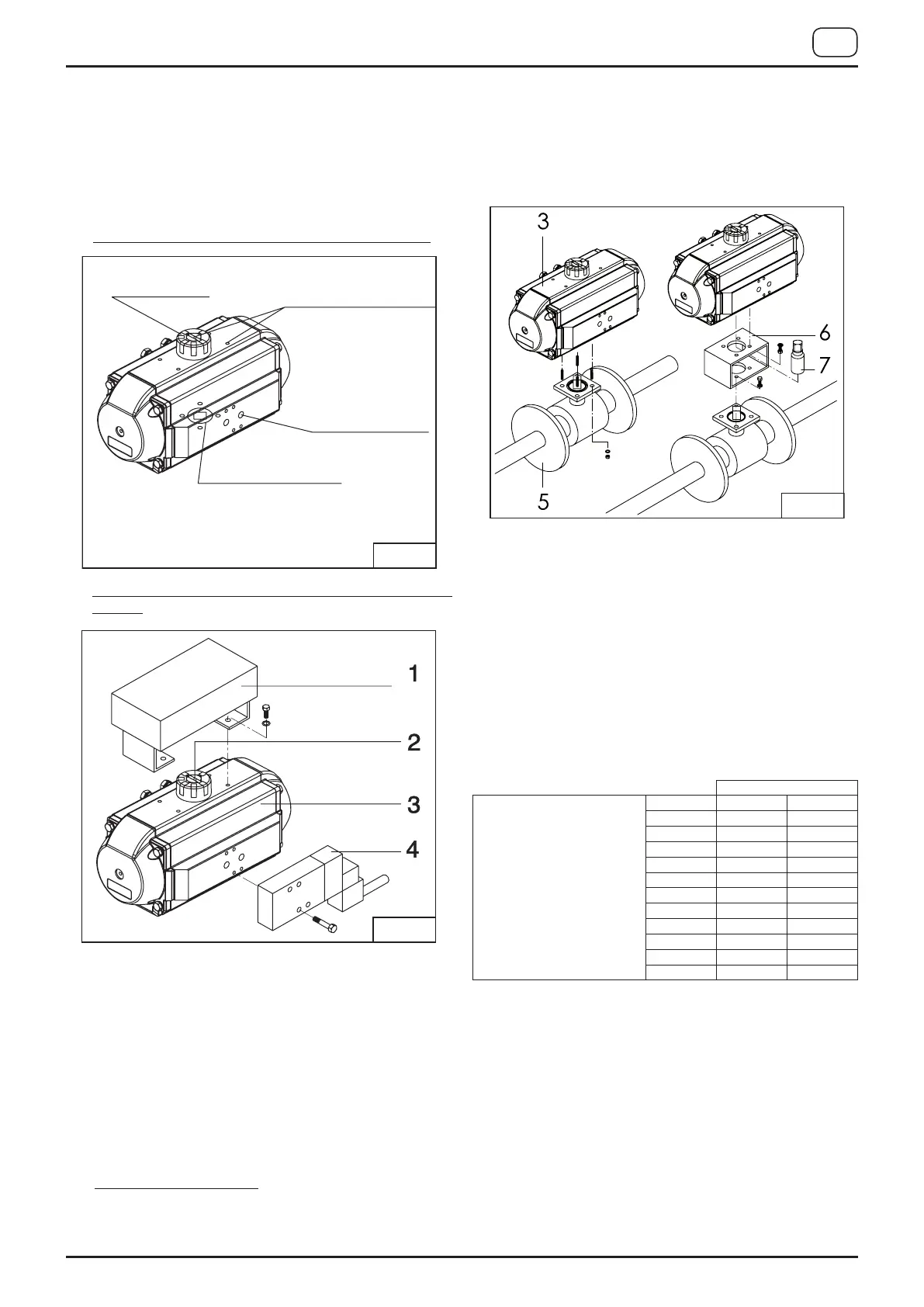
5.3) Assembly of accessories: solenoid valves and switchboxes,
figure B:
• Solenoid valve mounting:
Before mounting a solenoid valve, ensure that the actuator is
in its normal position (closed position) with pistons inwards.
For standard rotation type “ST” (clockwise to close) as-
sembly: the groove on the drive shaft or on the position
indicator 2 must be horizontal to the longitudinal axis of
the actuator in closed position.
Fit the solenoid valve 4 onto the actuator 3 using the pro-
vided screws (max. tightening torque see table).
• Switchbox mounting:
Fit the switchbox and bracket 1 onto the actuator 3 using
four provided screws (max. tightening torque see table).
5.4) Assembly of Valve Fig. C:
Before installing the actuator onto a valve, verify that the
maximum transmissible torque for available ISO Flange and
drive shaft connection is not exceeded according to ISO
5211 considering: the maximum actuator output torque,
the maximum air supply pressure and the maximum valve
torque. Before proceeding with the assembly of the actua-
tor onto the valve, be sure that the actuator operates in
the desired direction of rotation when pressurised and both
actuator / valve are in the correct position.
Important: when using a spring return actuator for a fail
safe operation, ensure that when air or electricity failure oc-
curs the direction of rotation is correct for your application.
Fit the actuator 3 onto the valve 5. It is possible to assem-
ble the valve onto the actuator in two ways:
•
Direct-mount: fit the stem of the valve 5 directly into the fe-
male connection of the actuator 3 and bolt together through
the valve ISO pad (max. tightening torque see table).
•
Bracket-mount: mounting with a bracket 6 and coupling 7,
the bracket is bolted to the actuator / valve to join them to-
gether and the coupling is used to connect the actuator out-
put drive to the valve stem (max. tightening torque see table).
6) MAINTENANCE INSTRUCTION
With the information given below, AIR TORQUE provides
the end user with all the required information necessary
for maintenance. Under normal conditions, the actuator re-
quires only periodic observation to ensure proper operation.
Maintenance (disassembly, maintenance and rebuilding) of
AIR TORQUE actuators is allowed only to AIR TORQUE
personnel or properly instructed personnel. In case of con-
troversy the product guarantee will expire! Spare kits for
maintenace are available to replace all seals and bearings
(soft parts indicated into the table), that may be necessary
between 200.000 and 1.000.000 cycles depending on oper-
ating and environmental conditions and actuator size.
Position indicator
VDI/VDE 3845
Pressure connections
VDI/VDE 3845
Ancillaries attachment
ISO 5211/ DIN 3337
Valve actuator attachment
Nm
Tightening torque table for
DRY (A) and LUBRICATED (B)
condition.
M… A B
M5 5 ÷ 6 4 ÷ 5
M6 10 ÷ 11 7 ÷ 8
M8 23 ÷ 25 18 ÷ 20
M10 48 ÷ 52 34 ÷ 36
M12 82 ÷ 86 60 ÷ 64
M14 132 ÷ 138 96 ÷ 102
M16 200 ÷ 210 150 ÷ 160
M20 390 ÷ 410 290 ÷ 310
M24 675 ÷ 705 500 ÷ 530
M30 (A.. 50) 620 ÷ 650 470 ÷ 500
M30 (A.. 70) 1340 ÷ 1400 1000 ÷ 1050
 Loading...