Mounting Location
• The water flowing across the hull
must
be smooth with a
minimum of bubbles and turbulence (especially at high speeds).
Caution
: DO NOT MOUNT near water intake or discharge
openings, or behind strakes, fittings, or hull irregularities.
• The multisensor
must
be continuously immersed in water.
• The transducer beam
must
be unobstructed by the keel or
propeller shaft(s).
• Choose a location away from interference caused by power and
radiation sources such as: the propeller(s) and shaft(s), other
machinery, other echosounders, and other cables. The lower
the noise level, the higher the echosounder gain setting that
can be used.
• Choose a location with a minimum deadrise angle, so the
transducer beam will be aimed at the bottom.
• Choose an accessible spot inside the vessel with adequate
headroom for the height of the housing, tightening the nuts, and
removing the insert. Allow a minimum of 280mm (11").
Hull Types
(see Figure 2)
•
Displacement hull powerboats
—Locate amidships near the
centerline. The starboard side of the hull where the propeller blades
are moving downward is preferred.
•
Planing hull powerboats
—Mount well aft, on or near the centerline,
and
well inboard of the first set of lifting strakes
to insure that the
multisensor will be in contact with the water at high speeds. The
starboard side of the hull where the propeller blades are moving
downward is preferred.
Outboard and I/O
—Mount just forward of the engine(s).
Inboard
—Mount well ahead of the propeller(s) and shaft(s).
Stepped hull
—Mount just ahead of the first step.
Boat capable of speeds above 25kn
(29MPH)—Review the
installation location and operating results of similar boats before
proceeding.
•
Fin keel sailboats
—Mount on or as close as possible to the
centerline and forward of the fin keel 300–600mm (1–2').
•
Full keel sailboats
—Locate amidships and away from the keel at
the point of minimum deadrise.
Installation
Cored fiberglass hull
—Follow separate instructions on page 3.
Hole Drilling
Warning
: Always wear safety goggles and a dust mask.
1. Drill a 3mm or 1/8" pilot hole from inside the hull. If there is a rib,
strut or other hull irregularity near the selected mounting
location, drill from the outside.
2. Using the appropriate size hole saw, cut a hole from outside the hull.
Flush housing
—Use a countersink tool to make a “seat” in the hull.
3. Sand and clean the area around the hole, inside and outside, to
ensure that the sealant will adhere properly to the hull. If there is
any petroleum residue inside the hull, remove it with either mild
household detergent or a weak solvent (alcohol) before sanding.
Metal hull
—Remove all burrs with a file and sandpaper.
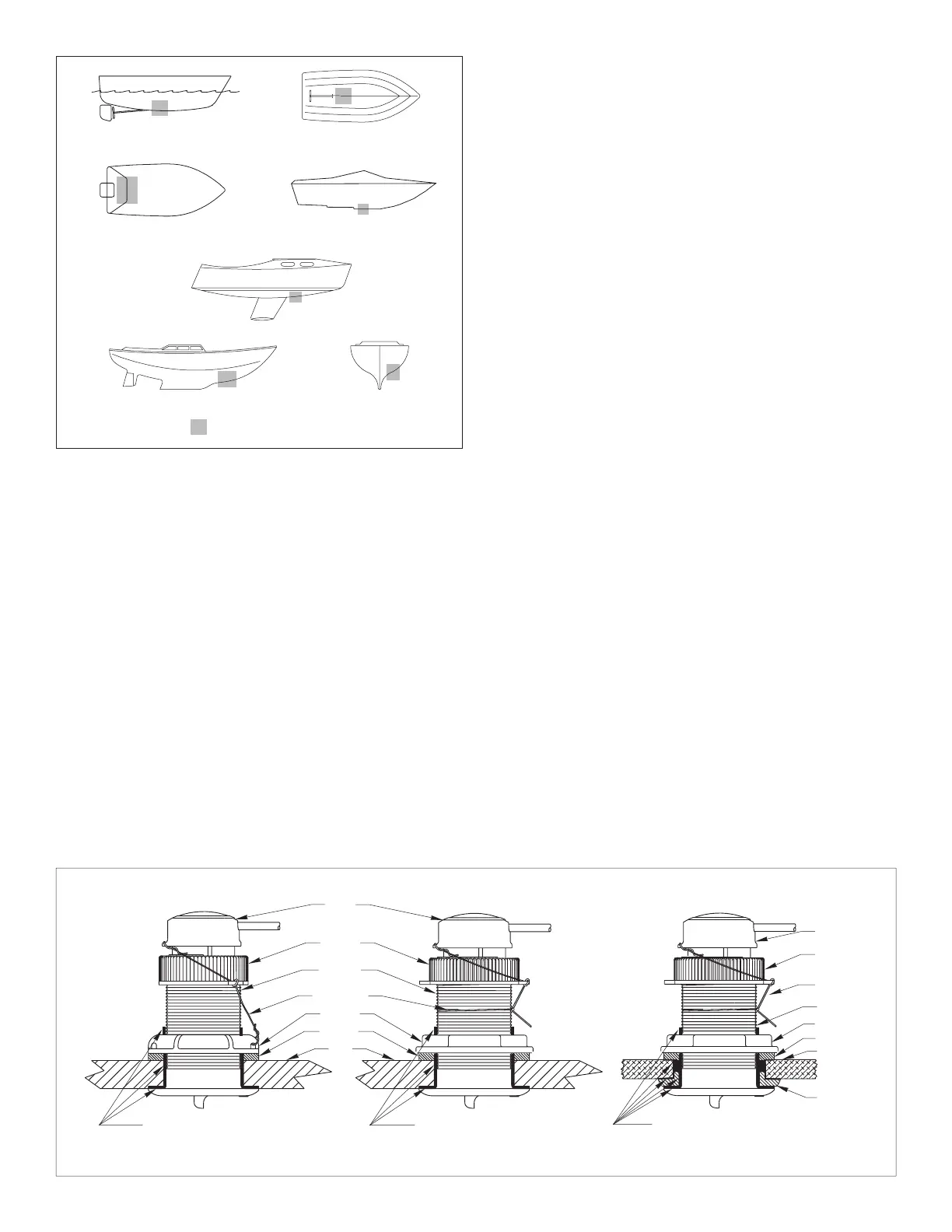
Bedding
Caution
: A stainless steel housing must be isolated from a metal
hull to prevent electrolytic corrosion.
Apply a 2mm (1/16") thick layer of marine sealant around the lip of
the housing that contacts the hull and up the sidewall of the
housing (see Figure 3). The sealant
must
extend 6mm (1/4")
higher than the combined thickness of the hull, the washer(s), and
the hull nut. This will ensure there is marine sealant in the threads
to seal the hull and to hold the hull nut securely in place.
2
planing hulls
Figure 2.
full keel sailboats
large displacement hulls
small displacement hulls
fin keel sailboats
Best location for multisensor
Copyright © 2005 Airmar Technology Corp.
stepped hull
outboard and I/O
marine sealant on lip and
Figure 3. Bedding and installing
cap nut
washer
hull
plastic housing
safety wire
housing
hull nut
insert
marine sealant on lip
stainless steel housing in metal hullmetal housing in
non
-metal hull
isolation
ring
washer
sidewall of housing
(plastic)
marine sealant on lip
cap nut
hull
safety wire
housing
insert
(plastic)
(metal)
hull nut
Copyright © 2005, 2006 Airmar Technology Corp.
BOW
➤
and sidewall of housing
and sidewall of housing
and isolation ring where it contacts the hull
P17 shown
B17 shown SS577 shown
 Loading...