4/32
Figures
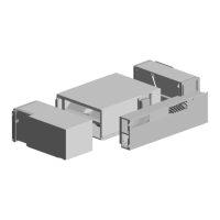
Figure 1 - The units composition. Seen from the inside (left picture) and outside (right picture) ................................................... 10
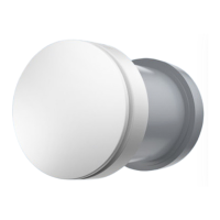
Figure 2 - The visible part (seen from inside) ................................................................................................................................................................... 10
Figure 3 - The air current from the unit ................................................................................................................................................................................. 11
Figure 4 - The ventilation unit half out of the wall mount.......................................................................................................................................... 11
Figure 5 - Wall mount and the outside part........................................................................................................................................................................ 11
Figure 6 - Button for turning on/off and changing the ventilation step ........................................................................................................... 12
Figure 7 - Visual signal of the ventilation level seen on the “back wall” through the grille ..................................................................13
Figure 8 - Turn off the unit ............................................................................................................................................................................................................14
Figure 9 - Plastic bag for sealing ...............................................................................................................................................................................................14
Figure 10 - The plastic bag is used to cover the unit ................................................................................................................................................... 15
Figure 11 - Secure the bag with the rubber band ........................................................................................................................................................... 15
Figure 12 - Cleaning of the visible internal part ............................................................................................................................................................... 16
Figure 13 - Turn off the unit .......................................................................................................................................................................................................... 17
Figure 14 - Press down on the spring catches ................................................................................................................................................................. 17
Figure 15 - Take the ventilation system out and place it down on the internal cover ............................................................................ 18
Figure 16 - Carefully vacuum the hole in the wall as well as the coarse filter in the back .................................................................... 18
Figure 17 - The ventilation unit is placed back in the wall......................................................................................................................................... 18
Figure 18 - Clean the internal coarse filter ......................................................................................................................................................................... 19
Figure 19 - Reattach the internal cover ............................................................................................................................................................................... 19
Figure 20 - Turn off the unit ........................................................................................................................................................................................................ 20
Figure 21 - Change the internal filter ..................................................................................................................................................................................... 20
Figure 22 - Press down on the spring catches ................................................................................................................................................................. 21
Figure 23 - Take the ventilation system out and place it down on the internal cover ............................................................................ 21
Figure 24 - Changing the outside filter ................................................................................................................................................................................ 22
Figure 25 - The ventilation unit is placed back in the wall ........................................................................................................................................ 22
Figure 26 - Resetting the filter indicator ............................................................................................................................................................................. 23
Figure 27 - Start the unit ................................................................................................................................................................................................................ 24
Figure 28 - Turn off the unit ........................................................................................................................................................................................................ 25
Figure 29 - Remove the internal filter ................................................................................................................................................................................... 26
Figure 30 - Press down on the spring catches ............................................................................................................................................................... 26
Figure 31 - Take the ventilation system out and place it down on the internal cover ............................................................................ 26
Figure 32 - Remove the outside filter ................................................................................................................................................................................... 27
Figure 33 - Carefully clean the ventilation unit with compressed air ............................................................................................................... 27
Figure 34 - Place a new outside filter in the ventilation unit .................................................................................................................................. 28
Figure 35 - The ventilation unit is placed back in the wall ....................................................................................................................................... 28
Figure 36 - Place a new internal filter in the ventilation unit .................................................................................................................................. 28
Tables
Table 1 - Product name and type ................................................................................................................................................................................................ 8
Table 2 - Capacity, sound pressure, nominal current ..................................................................................................................................................... 8
Table 3 - Adjusting the ventilation step ................................................................................................................................................................................ 12
Table 4 - choosing the right ventilation step .....................................................................................................................................................................13
Table 5 - Overview of cleaning .................................................................................................................................................................................................. 16
Table 6 - Troubleshooting ............................................................................................................................................................................................................ 29
 Loading...