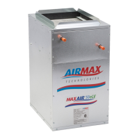
Do you have a question about the Airmax MaxAir 50eP2 and is the answer not in the manual?
Highlights the advantages of the MaxAir(e)™ Mini Ducted systems, focusing on venting flexibility and quiet operation.
Details the suitable applications for MaxAir(e)™ Mini Ducted systems, including retrofit and new construction projects.
Describes the insulated cabinet panels, durable finish, and mounting flexibility of the air handler unit.
Details the construction of heating coils, emphasizing copper, lead-free solder, and high-density aluminum fins.
Lists and describes available accessories, including check valves, for the air handler system.
Guidance on determining the number of diffusers needed based on heat loss/gain calculations for optimal system performance.
Provides notes on diffuser placement, velocity effect, and optimal locations for comfort and air mixing.
Offers guidance on trunk duct layout, aiming for self-balancing systems and optimal branch run lengths.
Discusses key factors for indoor air quality, including filtration, humidity control, and fresh air makeup.
Provides instructions and precautions for mounting the MaxAir(e)™ combo air handler in various configurations.
Details the installation requirements for domestic water piping, including drain valves and isolation valves.
Gives recommendations for diffuser placement to maximize system benefit and occupant comfort.
Explains the process of evacuating the system to 500 microns and charging it with refrigerant.
Diagram showing the layout of the DCC7235 microcontroller-based electronic volume controller.
Specifies the 24VAC power requirements, transformer rating, and voltage/current limits for the control.
Details the various control system inputs, including 0-10VDC command and switched 24VAC inputs.
Describes the system outputs, including connections to EC motors and high voltage relay outputs.
Explains how to use DIP switches to select flow volume levels for discrete input states.
Ensures all electrical connections are tight, proper airflow, and no damaged ducts before operation.
Explains how zone panels work with multi-stage HVAC equipment for comfort and economy.
Details the indicators on the 2-zone panel for monitoring dampers and equipment status.
Provides a table for configuring the 2-zone panel via DIP switches for various HVAC system types.
Details DIP switch settings for the 3-zone panel, including additional staging features.
Recommends monthly inspection, cleaning, or replacement of filters to maintain performance.
Details maintenance for the circulating pump, noting its water-lubricated nature and potential issues.
Troubleshooting steps for common issues causing insufficient or no heat output from the system.
Provides guidance for diagnosing and resolving issues within the zone control system.
A step-by-step guide to troubleshoot problems with the 2-zone panel and its connected components.
Details the specific wiring modifications required for a two-zone system with a heat pump.
Details the specific wiring modifications required for a three-zone system with a heat pump.
Provides a table with dimensions and specifications for horizontal air flow evaporator coils.
Illustrates a typical open loop system diagram for the air handler and domestic hot water storage.
Illustrates a typical closed loop system diagram for the air handler and domestic hot water storage.
| Brand | Airmax |
|---|---|
| Model | MaxAir 50eP2 |
| Category | Air Handlers |
| Language | English |

 Loading...