Do you have a question about the Airmax MaxAir 50e LV and is the answer not in the manual?
Guidance on selecting the correct MaxAir™ fan coil model based on heat load.
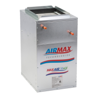
Instructions for mounting the air handler in various configurations, including strap use.
Guidelines for installing 1/2" sediment faucet, isolation valves, and copper piping.
Details on accessory slab cooling coil, factory-installed TX valve, and drain pan requirements.
Guidelines for placing the fan coil unit based on layout and system design.
Installing fan coil for DX refrigerant cooling, ensuring proper condensate drainage.
Locating the outdoor unit and maintaining recommended clearances for airflow.
Proper installation and insulation of TXV bulb and frost thermostat control.
Guidelines for installing refrigeration piping, including insulation and traps.
Procedures for pressurizing, leak testing, and charging the refrigeration system.
Terminal strip locations for electrical connections like power, pump, and thermostat.
Microcontroller-based volume controller for fan coils, furnaces, and other systems.
Details on 0-10VDC commands and discrete 24VAC inputs for system control.
Configuring the input mode for discrete or 0-10V variable control.
Configuring single-stage and two-stage heating system operation.
Setting up timed two-stage heating operation with thermostat inputs.
Importance of filter maintenance and potential warranty voiding.
Troubleshooting steps for a pump that fails to start or sticks.
Addressing noise issues with the external pump, often related to air.
Diagnosing and resolving issues with insufficient or no heat output.
Resolving issues where the fan operates for cooling but not heating.
Investigating causes for heating during the off cycle, like thermal siphoning.
Diagram illustrating an open loop system for heating and domestic hot water.
Diagram showing a closed loop system for heating and domestic hot water.
| Model | MaxAir 50e LV |
|---|---|
| Cooling Capacity | 50, 000 BTU/h |
| Voltage | 208-230V |
| Motor Type | ECM |
| Category | Air Handler |
| Airflow | 2000 CFM |
| Phase | Single |
| Filter Type | MERV 8 |