AB1561 Headset Reference Design
User Guide
© 2020 Airoha Technology Corp.
This document contains information that is proprietary to Airoha Technology Corp. (“Airoha”) and/or its licensor(s).
Any unauthorized use, reproduction or disclosure of this document in whole or in part is strictly prohibited.
1. Introduction
The man-machine interface (MMI) layer is intended to offer a well-organized interface that makes control profile
services such as HFP, A2DP, and AVRCP more intuitive. The MMI layer also provides a robust system environment
which protects users from a negative experience (e.g., crash situation).
This guide is written to help users easily and completely understand MMI layer functionality.
1.1. Platform architecture
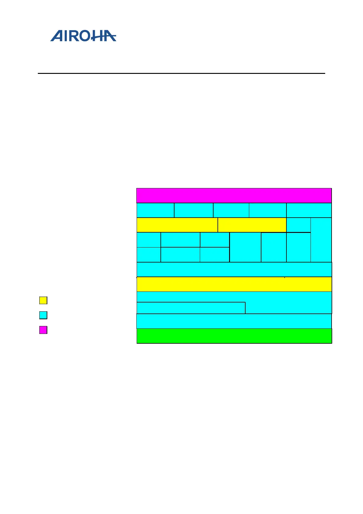
Figure 1. Software architecture shows that the software architecture is made up of several components which are
also divided into three different groups: Airoha Defined Interface component; Bluetooth Defined Component; and
Customer Defined Component. MMI is the only component in the Customer Defined component. It is also the
topmost layer and is completely controlled by users. Moreover, MMI coordinates the interface and allows all
profiles to operate together.
AVRCP
Hardware
LC
LM
HCI Middleware
L2
CAP
RFCOMM
SDP
MMI
Profile Manager
Data Center
SDAP
SPP
Host
Controller
Applications
Middle Profiles
Airoha Defined Interface Component
Bluetooth Defind Component
Customer Defind Component
{
{
AVDTP
GAVDP
AVCTP
GAP
ATT
SM
A
2
DPHandsfree
Headset
GATT
BLE Profiles
Figure 1. Software architecture
1.2. EVK components
When users start using the MMI functionality, there are some signals they can recognize to verify whether the
corresponding functionality is correctly operating. Besides, users must use some EVK components to also make use
of the MMI functionalities. Therefore, this section introduces those components that are used to trigger MMI or
show the MMI functionality.
There are four different colors to indicate the different EVK component groups as shown in Figure 2. EVK
components.