EACH WIRE NUT (WIRE CONNECTOR) SUPPLIED
WITH THIS FAN IS DESIGNED TO ACCEPT UP TO
ONE 12 GAUGE HOUSE WIRE AND TWO WIRES
FROM THIS FAN. IF YOU HAVE LARGER THAN
12 GAUGE HOUSE WIRING OR MORE THAN
ONE HOUSE WIRE TO CONNECT TO THE FAN
WIRING, CONSULT AN ELECTRICIAN FOR THE
PROPER SIZE WIRE NUTS TO USE.
USE THE PLASTIC WIRE CONNECTORS
SUPPLIED WITH YOUR FAN. SECURE THE
CONNECTORS WITH ELECTRICAL TAPE AND
ENSURE THERE ARE NO LOOSE STRANDS OR
CONNECTIONS.
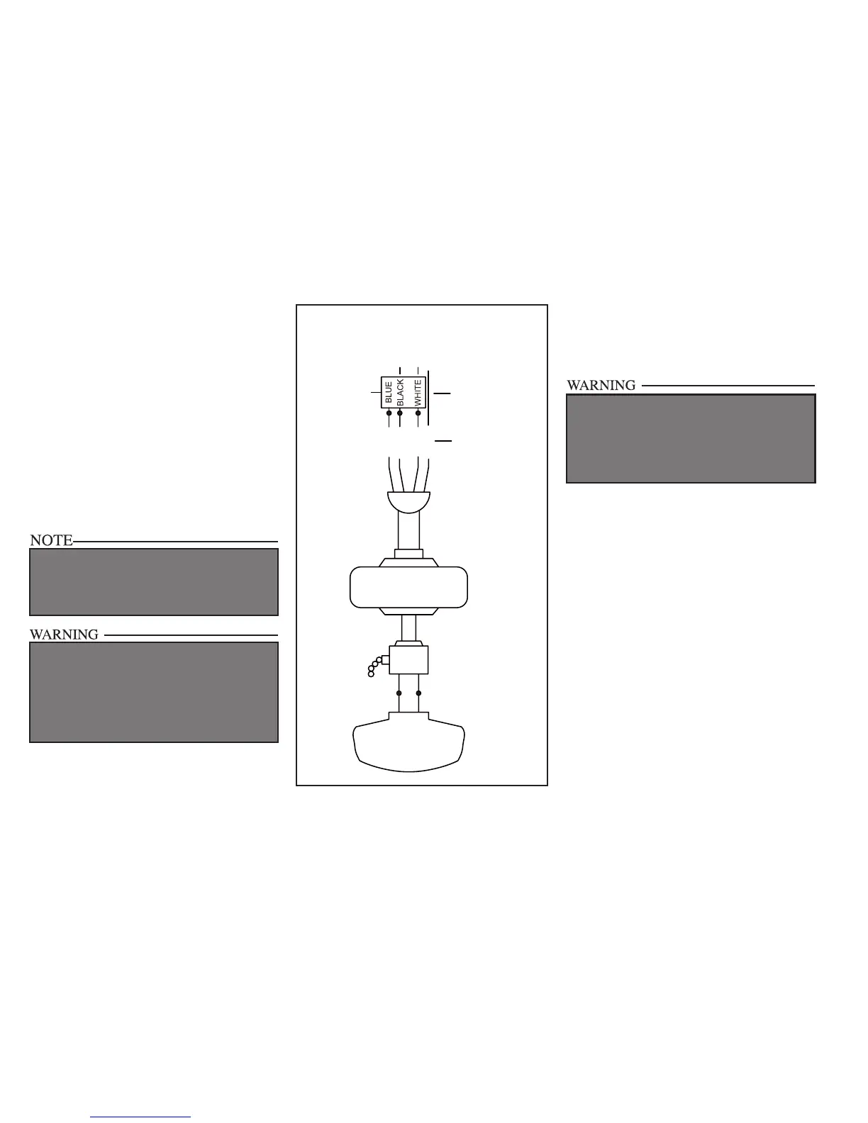
BLUE
BLACK
WHITE
GREEN
BLUE
BLACK
WHITE
WHITE
SUPPLY CIRCUIT
BLACK
WHITE
Grounding
Conductor
Green
Grounding
Lead
Remote
Receiver
Figure 10
6.
5. Connect the receiver black wire to the
supply black (hot) wire using a wire nut
(Figure 10).
6. Connect the receiver white wire to the
supply white (neutral) wire using a wire nut
(Figure 10).
7. After connecting the wires, spread them
apart so that the green and white wires are
one side of the electrical box and the black
wire is on the other side.
8. Turn the wire connecting nuts upward and
carefully push the wiring into the electrical
box.
Finishing the Fan
Installation
STANDARD CEILING MOUNTING
1. Align the locking slots of the ceiling
canopy with the two screws in the mounting
plate. Push up to engage the slots and turn
clockwise to lock in place. Immediately
tighten the two mounting screws rmly.
2. Install the remaining two mounting
screws into the holes in the canopy and
tighten rmly.
3. Install the decorative canopy ring by
aligning the ring’s slots with the screws
in the canopy. Rotate the ring counter-
clockwise to lock in place.
4. You may now proceed to attaching the
fan blades.
WHEN USING THE STANDARD BALL/DOWNROD
MOUNTING, THE TAB IN THE RING AT THE
BOTTOM OF THE MOUNTING PLATE MUST
REST IN THE GROOVE OF THE HANGER BALL.
FAILURE TO PROPERLY SEAT THE TAB IN THE
GROOVE COULD CAUSE DAMAGE TO WIRING.