AirScape 1.0 & 1.7 Whole House Fan Installation Manual, 03222018
©AirScape, Inc., 2018. All Rights Reserved.
Page 5
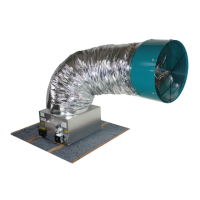
All wiring connections to the fan assembly are made at the fan-mounted electrical box. These are a 10 ft, black,
factory-installed power cord, and three RJ45 (“ethernet”) ports for connecting the fans controls and accessories,
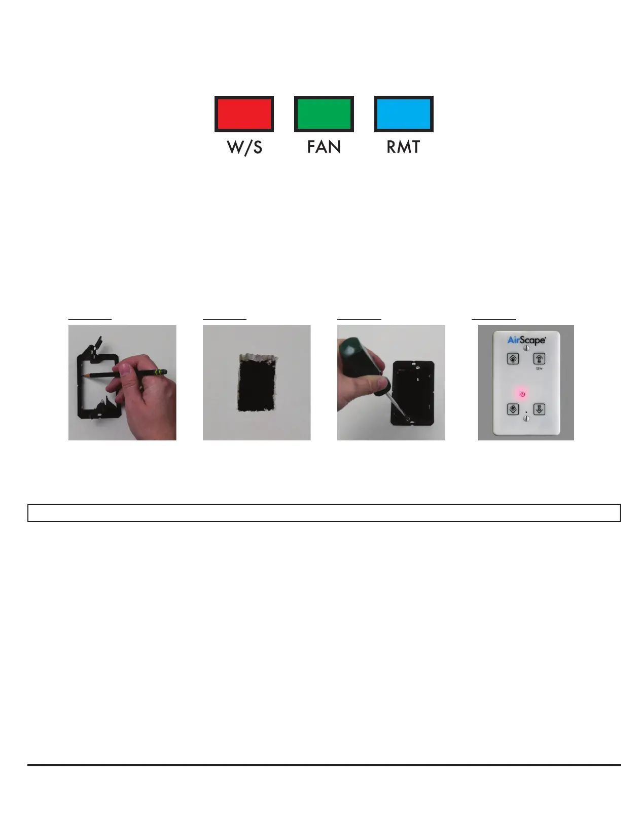
labled as follows:
First, locate the desired location for the Digital Touch Controller. Install the mounting bracket according to Figures
A–C below.
Return to the attic and connect the red CAT5 cable to the RJ45 port on the fan electrical box labled W/S. Run
this cable from the electrical box to the location of the controller. NOTE: this is a low-voltage cable, DO NOT RUN
IT PARALLEL TO HIGH-VOLTAGE WIRING; building codes generally require low-voltage cable to be run through
shielded conduit.
Connect the CAT5 cable to the RJ45 port on the back of the Digital Touch Controller. Mount the controller’s face-
plate to the mounting bracket with the provided white screws, as shown below in Figure D.
Use the mounting
bracket as a template to
mark the hole location.
Figure A
Cut out the hole. Place the mounting bracket
and secure its locking tabs
by tightening the silver
screws
Figure B Figure C Figure D
Connect the CAT5 cable.
Mount the faceplate to the
bracket with the provided
white screws
WIRING & CONTROLS, cont.
WIRELESS REMOTE (NOT INCLUDED)
A wireless remote and AirScape’s “2nd Generation Control Package” are available accessories for this fan. The 2nd
Generation Controls include a webserver that allows you to operate your fan from any smartphone, tablet, or com-
puter with access to your home’s local area network (“LAN”); they are also necessary to use AirScape’s Tempera-
ture Sensor Package (“TSP”) and SafeSpeed™ Pressure Interlock accessories.
Neither of the wireless remote, nor the 2nd Generation Controls are included as part of this fan’s standard control
package. The yellow manual included with these accessories provides speci c instructions for their installation and
operation.
If purchased, the wireless remote recieve is connected to the fan-mounted electrical box at the blue RMT RJ45 port,
and the 2nd Generation Controls at the green FAN port.
 Loading...