EasyManua.ls Logo

Airwell AWAU-YDD009-H11 User Manual

Airwell AWAU-YDD009-H11
46 pages
To Next Page IconTo Next Page
Page #1 background imageLoading...
Page #1 background image
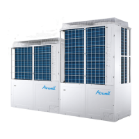
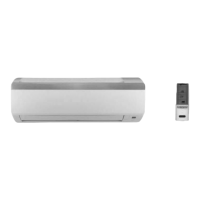
Indoor Units Outdoor Units
AWSI-HDD009-H11 AWSI-HED009-H11 AWAU-YDD009-H11
AWSI-HDD012-H11 AWSI-HED012-H11 AWAU-YDD012-H11
NOVEMBER – 2010
REFRIGERANT
R410A
HEAT PUMP
SM HDDHED 1-A.1 GB
Version: 1

Questions and Answers:

Airwell AWAU-YDD009-H11 Specifications

General IconGeneral
BrandAirwell
ModelAWAU-YDD009-H11
CategoryAir Conditioner
LanguageEnglish

Summary

1. INTRODUCTION

1.1 General

Overview of the HDD/HED DCI inverter air conditioner series for residential use.

1.2 Main Features

Highlights key technological innovations and benefits of the air conditioning units.

1.3 Indoor Unit

Description of the wall-mounted indoor unit, its features, and filtration system.

1.4 Control

Details the microprocessor controller, remote control functions, and operation.

1.5 Outdoor Unit

Information on outdoor unit installation, materials, and internal components.

1.6 Tubing Connections

Specifies flare type interconnecting tubing and installation details.

1.7 Inbox Documentation

Lists the installation, operation, and remote control manuals supplied with each unit.

1.8 Matching Table

Table showing compatible indoor and outdoor unit model combinations.

2. PRODUCT DATA SHEET

2.1 HDD009 / HED009 // YDD 009

Detailed technical specifications for HDD009, HED009 indoor and YDD009 outdoor units.

2.2 HDD012 / HED012 // YDD 012

Detailed technical specifications for HDD012, HED012 indoor and YDD012 outdoor units.

3. RATING CONDITIONS

3.1 Operating Limits

Defines the operational limits including temperature and voltage for the units.

3.1.1 R410A

Specific operating limits for units using R410A refrigerant.

4. OUTLINE DIMENSIONS

4.1 Indoor Unit: HDD009, HDD012, HED009, HED012

Provides detailed physical dimensions and diagrams for all indoor unit models.

4.2 Outdoor Units: YDD009, YDD012

Provides detailed physical dimensions and diagrams for YDD009/YDD012 outdoor units.

5. PERFORMANCE DATA & PRESSURE CURVES

5.1 HDD009, HED009

Performance data and pressure curves specifically for HDD009 and HED009 models.

5.1.1 Cooling Capacity (kW) – Run Mode

Cooling capacity charts for HDD/HED009 at various temperature conditions.

5.1.2 Capacity Correction Factors

Factors to adjust cooling capacity based on outdoor temperature for HDD/HED009.

5.1.3 Heating Capacity (kW) - Run Mode

Heating capacity charts for HDD/HED009 at various temperature conditions.

5.1.4 Capacity Correction Factors

Factors to adjust heating capacity based on outdoor temperature for HDD/HED009.

5.1.5 Model: HDD009, HED009

Charts showing suction pressure and input current for HDD/HED009 cooling mode.

5.1.5.1 Cooling

Graphs of suction pressure and input current vs. outdoor temperature for cooling.

5.1.5.2 Heating

Graphs of discharge pressure and input current vs. outdoor temperature for heating.

5.2 HDD012, HED012

Performance data and pressure curves specifically for HDD012 and HED012 models.

5.2.1 Cooling Capacity (kW) - Run Mode

Cooling capacity charts for HDD/HED012 at various temperature conditions.

5.2.2 Capacity Correction Factors

Factors to adjust cooling capacity based on outdoor temperature for HDD/HED012.

5.2.3 Heating Capacity (kW) - Run Mode

Heating capacity charts for HDD/HED012 at various temperature conditions.

5.2.4 Capacity Correction Factors

Factors to adjust heating capacity based on outdoor temperature for HDD/HED012.

5.2.5 Model: HDD012, HED012

Charts showing suction pressure and input current for HDD/HED012 cooling mode.

5.2.5.1 Cooling

Graphs of suction pressure and input current vs. outdoor temperature for cooling.

5.2.5.2 Heating

Graphs of suction pressure and input current vs. outdoor temperature for heating.

6. SOUND LEVEL CHARACTERISTICS

6.1 Sound Pressure Level

Describes the measurement methodology for sound pressure level.

6.2 Sound Pressure Level Spectrum (Measured as Figure 1)

Sound pressure level spectrum analysis for HDD/HED009 indoor units.

6.3 Outdoor units

Section dedicated to sound level characteristics of outdoor units.

6.4 Sound Pressure Level Spectrum (Measured as Figure 2)

Sound pressure level spectrum analysis for YDD009/YDD012 outdoor units.

7. ELECTRICAL DATA

7.1 Single Phase Units

Electrical specifications including power supply, current, and wiring for single-phase units.

8. WIRING DIAGRAMS

8.1 Indoor Units: HDD009, HDD012, HED009, HED012

Detailed wiring diagrams for all indoor unit models.

8.2 Outdoor Units: YDD009, YDD012

Detailed wiring diagrams for YDD009 and YDD012 outdoor units.

9. REFRIGERATION DIAGRAMS

9.1 HDD009 / HED009 // YDD009

Refrigeration circuit diagram for HDD/HED009 indoor units with YDD009 outdoor units.

9.2 HDD012 / HED012 // YDD012

Refrigeration circuit diagram for HDD/HED012 indoor units with YDD012 outdoor units.

10. TUBING CONNECTIONS

11. CONTROL SYSTEM

11.1 Electronic Control

Overview of the electronic control system for the air conditioner.

11.1.1 Abbreviations

Glossary of abbreviations used within the control system section.

11.1.2 System Operation Concept

Explains the master-slave interaction between indoor and outdoor unit controllers.

11.1.3 Compressor Frequency Control

Details the PI control scheme for managing compressor frequency.

11.1.3.1 Frequancy range

Specifies the minimum and maximum operating frequency limits for the compressor.

11.1.3.2 Frequency Changes Control

Defines the rate at which compressor frequency can change.

11.1.3.3 Compressor Starting Control

Describes the control logic when starting the compressor.

11.1.3.4 Minimum On and Off Time

Rules for minimum compressor ON and OFF times to protect the unit.

11.1.4 Indoor Fan Control

Methods for controlling indoor fan speed across different modes.

11.1.4.1 Turbo Speed

Operation of the high-speed Turbo fan mode via remote control.

11.1.5 Outdoor Fan Control

Control mechanisms for the outdoor fan motor.

11.1.5.1 OFAN Speed Type

Specifies the type of speed control for the outdoor fan.

11.1.5.2 General rules

General operating rules for the outdoor fan in different modes.

11.1.6 Refrigerant control

Details the system's refrigerant control method, using capillary.

11.1.7 Reversing Valve (RV) Control

Explains the control of the reversing valve for heating mode.

11.2 Fan Mode

Operating characteristics and temperature settings for Fan mode.

11.3 Cool Mode

Conditions and operations for the cooling mode.

11.3.1 Indoor Fan operation under Cool Mode

Indoor fan speed adjustments during cooling mode based on temperature differences.

11.4 Heat Mode

Conditions and operations for the heating mode.

11.4.1 Indoor Fan Control in Heat Mode

Controls for indoor fan speed during heating, including anti-cold air.

Anti-cold air function

Function to prevent cold air discharge during heating startup.

Residual heat blowing function

Function to use residual heat for blowing after compressor stops.

11.5 Auto Cool/Heat Mode

Automatic selection of operating mode based on room temperature.

11.6 Dry Mode

Operating conditions and fan speed in Dry mode.

11.7 Louver Control

Operation and states of the up and down swing louvers.

11.8 Clean function

Function to dry the indoor coil after cooling or dry modes to prevent mold.

11.9 Sleep function

Operation and temperature adjustments for the sleep mode.

11.10 I-Feel function

Function to maintain room temperature using remote control sensor data.

11.11 Protections

Overview of the four protection codes that monitor system operation.

11.11.1 Indoor Coil Defrost Protection

Protection mechanism to prevent the indoor coil from freezing.

11.11.2 Indoor Coil over Heating Protection

Protection against overheating of the indoor coil during operation.

11.11.3 Compressor over Heating Protection

Protection against excessive internal temperature of the compressor.

11.11.4 Compressor over Current Protection

Protection against excessive current drawn by the compressor.

11.11.5 Outdoor Coil Deicing Protection

Protection for heat pump models to prevent outdoor coil icing.

11.11.5.1 Deicing Starting Conditions

Conditions required for the deicing cycle to initiate.

11.11.5.2 Deicing Protection Procedure

Sequence of operations during the deicing protection mode.

11.11.5.3 Exiting Deicing

Criteria for ending the deicing cycle and returning to normal operation.

11.12 Operating the Unit from the ON/OFF Button

How to operate the unit using the ON/OFF button and auto mode selection.

11.13 Indoor Unit Controllers and Indicators

Schematic of the indoor unit display, LEDs, and button functions.

11.14 Test Mode

Procedures for entering and operating the unit in test mode for capacity checks.

11.14.1 Entering Test Mode

Steps to activate test mode using remote control settings.

11.14.2 Unit Operation in Test Mode

How compressor frequency and fan speed behave during test mode.

11.15 Characteristics of sensor

General section on sensor characteristics.

11.15.1 RAT / OAT

Resistance-temperature chart for Room/Outdoor Air Temperature sensors.

11.15.2 ICT / OCT

Resistance-temperature chart for Indoor/Outdoor Coil Temperature sensors.

11.15.3 CTT

Resistance-temperature chart for Compressor Temperature sensors.

12. TROUBLESHOOTING

12.1 ELECTRICAL & CONTROL TROUBLESHOOTING

Troubleshooting guide for electrical and control system issues.

12.1.1 Precautions before Performing Inspection or Repair

Essential safety precautions to follow during inspection and repair.

12.1.2 Confirmation

Steps to confirm power supply and voltage before troubleshooting.

12.1.3 Judgment by Indoor/Outdoor Unit Diagnostics

Using unit diagnostics and error codes for fault identification.

Failure Codes and Possible Reasons

Lists common error codes (E2, E4-E6, EE, F0-F5, H3-H7, Lc) and their potential causes.

Additional Error Codes and Possible Reasons

Lists additional error codes (P7-P8, PH, PL, U1, U5, U7, UA, UF, UH, UU) and their causes.

12.1.4 Checking the refrigeration system

Procedures for checking system pressures and thermodynamic measures.

12.2 Simple procedures for checking the Main Parts

Basic troubleshooting steps for major components like voltage, power input, fan, compressor, and valve.

13. EXPLODED VIEWS AND SPARE PARTS LISTS

13.1 Indoor Unit: HDD009, HED009

Exploded view and parts list for HDD009, HED009 indoor units.

13.3 Indoor Unit: HDD012, HED012

Exploded view and parts list for HDD012, HED012 indoor units.

13.5 Outdoor Unit: YDD009, YDD012

Exploded view for YDD009, YDD012 outdoor units.

13.6 Outdoor Unit: YDD009 Parts List

Detailed parts list for YDD009 outdoor unit.

13.7 Outdoor Unit: YDD012 Parts List

Detailed parts list for YDD012 outdoor unit.

APPENDIX A

INSTALLATION AND OPERATION MANUAL

Reference to the separate Installation and Operation Manuals for the units.

Related product manuals