24
Split system gainable à pression -
Ductable pressurized split system -
Split-system für Kanalanschluß unter Druck
L1
N
6
8
9
123456 89
1
2N
3N
4
5
N
6
8
9
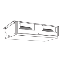
Alimentation électrique des unités.
Interconnexion
Power Supply of the Units - Interconnection
Modèles GC17-22-26/CD à climatisation seule
et pompe à chaleur.
Alimentation par l’unité intérieure.
Unité intérieure
Indoor unit
Innenteil
CD17
CD22
CD26
Accès au tableau électrique 2 vis dans la partie inférieure Entrées de câbles
en partie inférieure
Access to terminal box 2 screws at the bottom
Cable entry by the bottom
Zugang zu der Schalttafel 2 Schrauben im unteren Abschnitt. Kabeleintritt
unten.
Unité extérieure
Outdoor unit
Außenteil
GC17 / GC17RC
GC22 / GC22RC
GC26 / GC26RC
NOTES:
- The interconnection between contacts 8-9 and the outdoor
temperature probe must be made using 2 x 0.5 mm² cable
independent of the rest of the connections.
- Contacts 5/5 are interconnected only for BC systems (with
heat pump).
NOTES :
- L’interconnexion entre les bornes 8-9/Sonde extérieure doit
être effectuée avec un câble de 2x0,5mm² indépendam-
ment du reste des connexions.
- L’interconnexion entre les bornes 5/5 est effectuée unique-
ment pour les unités Réversibles.
Unité intérieure
Indoor unit
Innenteil
GC17-22-26/CD systems, air conditioner alone
and with heat pump.
Power supply via the indoor unit.
Sectionneur NON fourni
Section switch NOT supplied
Trennschalter NICHT geliefert
Stromversorgung der Geräte - Schaltung
Modelle GC17-22-26/CD Klimagerät ohne
Wärmepumpe und mit Wärmepumpe.
Versorgung über das Innenteil.
Accès au tableau électrique 2 vis dans la partie
inférieure Entrées de câbles en partie inférieure
Access to terminal box 2 screws at the bottom
Cable entry by the bottom
Zugang zu der Schalttafel 2 Schrauben im unteren
Abschnitt. Kabeleintritt unten.
HINWEISE:
- Die Verbindung der Klemmen 8-9 / Temperaturfühler außen
muß, unabhängig von den übrigen Verbindungen, mit einem
Kabel 2x0,5 mm2 erfolgen.
- Die Verbindung zwischen den Klemmen 5/5 erfolgt nur bei
den Geräten mit Wärmepumpe.
Unité extérieure
Outdoor unit
Außenteil
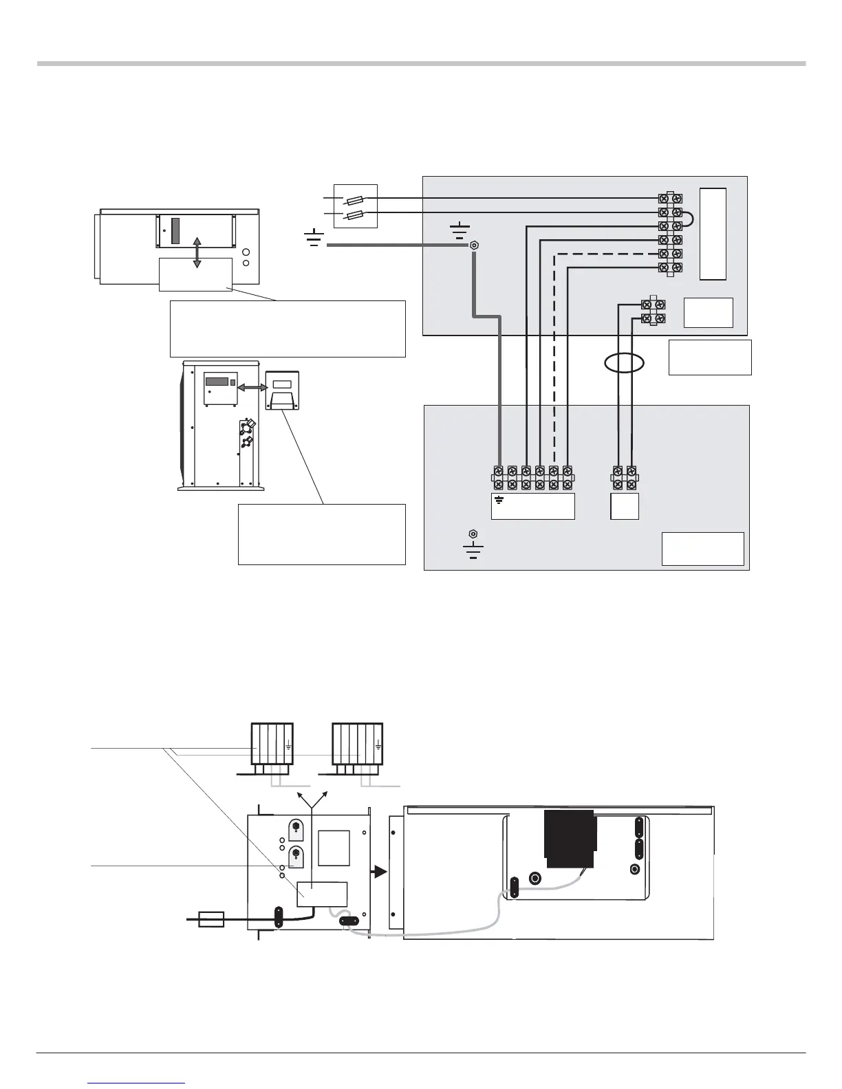
KIT CHAUFFAGE EN GAINE
Modeles: CD 17/22/26/35/43/50/60
x
x
x
x
FC M
FC
A
N
L1
10 11
L3
10
11L2
L1
x
x
x
x
x
x
Réarmement manuel
Bornier
1N~230V 50Hz 3N~400V 50Hz
Manual reset
Manuelles Wiedereinschalten
Terminal block
Klemmenleiste
DUCT HEATING KIT
Models: CD 17/22/26/35/43/50/60
* Separate power supply cable: not supplied
** Protective fuse mandatory : not supplied
EINBAUSATZ KANALHEIZUNG
Modelle : CD 17/22/26/35/43/50/60
* unabhängiges Anschlußkabel – nicht geliefert
** Schmelzsicherung erforderlich – nicht geliefert
*
*
**
SONDE
EXTERIEURE
* Câble d'alimentation indépendant - non fournit
** Protection par fusible obligatoire - non fournit
Voir spécifications électriques page 4
}
}
}
See electrical specifications, p. 4
Siehe elektrische Spezifikation Seite 4