EasyManua.ls Logo

Airwell DLF 18 DCI User Manual

Airwell DLF 18 DCI
102 pages
To Next Page IconTo Next Page
Page #1 background imageLoading...
Page #1 background image
REFRIGERANT
R410A
HEAT PUMP
ECO DESIGN 2014
DLF DC Inverter Series
201
SM DLF 1-A.1 GB
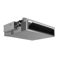
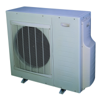
Indoor Units Outdoor Units
DLF
18 DCI YBDE018-H11
DLF
24 DCI YBDE024-H11

Questions and Answers:

Airwell DLF 18 DCI Specifications

General IconGeneral
BrandAirwell
ModelDLF 18 DCI
CategoryInverter
LanguageEnglish

Summary

Introduction to DLF DC Inverter Series

1.1 General Overview and Compatibility

Overview of the DLF DC INVERTER split unit range and remote control compatibility.

1.2 Main Features and Technology

Highlights key technological and system features of the DLF DC INVERTER series.

1.3 Indoor Unit Features

Details of the DLF DCI indoor unit's design and features.

1.4 Filtration System

Information about the unit's filtration system and filter accessibility.

1.5 Control System Overview

Explanation of the indoor unit's control system and remote control.

1.6 Outdoor Unit Features

Features and installation aspects of the DCI outdoor units.

1.7 Inbox Documentation Details

Details on the documentation included with each unit.

1.8 Unit Matching Table

Table showing compatible indoor and outdoor unit pairings.

Product Data Sheet

2.1 DLF 18 DCI Specifications

Technical specifications for the DLF 18 DCI model.

2.2 DLF 24 DCI Specifications

Technical specifications for the DLF 24 DCI model.

Rating Conditions and Operating Limits

3.1 Operating Limits

Defines the operational temperature and voltage limits for cooling and heating.

Outline Dimensions

4.1 Indoor Unit Dimensions

Provides physical dimensions and diagram for DLF 18 and 24 indoor units.

4.2 Outdoor Unit Dimensions

Shows physical dimensions and diagram for YBDE 018/024 outdoor units.

Performance Data and Pressure Curves

5.1 DLF 18 DCI Performance Data

Cooling and heating capacity data for DLF 18 DCI.

5.2 DLF 24 DCI Performance Data

Cooling and heating capacity data for DLF 24 DCI.

5.3 Tubing Length Correction Factors

Correction factors for cooling and heating based on tubing length.

5.4 Pressure Correction Factors for Tubing Length

Correction factors for pressure based on tubing length.

5.5 Temperature Correction Factors

Capacity correction factors based on outdoor temperature.

Airflow Curves and Correction Factors

6.1 DLF 18 DCI Airflow Chart

Airflow chart for DLF 18 DCI model.

6.2 DLF 24 DCI Airflow Chart

Airflow chart for DLF 24 DCI model.

6.3 DLF Unit Airflow Correction Factors

Correction factors for airflow rates across DLF units.

Sound Level Characteristics

7.1 Sound Pressure Level Measurement

Explanation of sound pressure level measurement methodology.

7.2 Indoor Unit Sound Pressure Spectrum

Sound pressure level spectrum for DLF 18 and DLF 24 indoor units.

7.3 Outdoor Unit Sound Characteristics

Introduction to outdoor unit sound characteristics.

7.4 Outdoor Unit Sound Pressure Spectrum

Sound pressure level spectrum for YBDE 018/024 cooling and heating.

Electrical Data

8.1 Single Phase Unit Specifications

Electrical specifications for single-phase DLF units.

Wiring Diagrams

9.1 Indoor Unit Wiring

Wiring diagram for DLF 18/24 DCI indoor units.

9.2 Outdoor Unit Wiring

Wiring diagram for YBDE 18/24 - H11 outdoor units.

9.3 1PH Indoor Unit Power Supply

Power supply wiring diagram for DLF 18 indoor units.

9.4 1PH Outdoor Unit Power Supply

Power supply wiring diagram for DLF 18, 24 outdoor units.

Refrigeration Diagrams

10.1 Heat Pump Model Diagram

Refrigeration diagram for heat pump models.

Tubing Connections

11.1 Tubing Connection Specifications

Details on tubing connections, torque values, and bending requirements.

Control System

12.1 Abbreviations

List of abbreviations used in the control system section.

12.2 Product Overview and Block Diagram

System overview with a block diagram of component interactions.

12.2.2 Controller Overviews and Models

Details on controller overviews and specific indoor/outdoor unit controllers.

12.2.2.3 & 12.2.2.4 Outdoor Unit Controllers

Specifics on main controllers for YBDE018/024 and YBDE030 outdoor units.

12.2.2.5 & 12.2.2.6 Display Board Information

Details on display boards, legends, and new versions.

12.2.3 Control Features Explained

Explanation of compressor, fans, EEV, HMI, dry contacts, and sensors.

12.2.3.9 & 12.2.3.10 Heater Operations

Explains the operation of base and crankcase heaters.

12.3 General Operating Rules and Power Up Sequence

Outlines general operating rules and the power-up sequence.

12.3.2 Indoor Unit Communication & Tests

Covers communication faults and system configuration tests.

12.3.4 Thermistor Measurements and Faults

Details thermistor default values, fault detection, and system reactions.

12.3.4.3 Thermistor Fault Operation

System operation modes when thermistor faults occur.

12.4 Indoor Unit Control and Load Calculation

Indoor unit control logic and load calculation methods.

12.4.2 Indoor Fan Control Modes

Details on indoor fan control modes and NLOAD limits.

12.4.2.2 & 12.4.2.3 Indoor Fan Control Modes

Specifics on indoor fan control for Cool and Heat modes.

12.4.3 Cooling Mode Operation

General description and control functions for cooling mode.

12.4.4 Heating Mode Operation

General description and control functions for heating mode.

12.4.4.4 Temperature Compensation & Auto Mode

Temperature compensation and automatic cooling/heating modes.

12.4.6 Dry Mode Operation

General description and control functions for dry mode.

12.4.7 Sleep Mode Operation

General description and control functions for sleep mode.

12.4.8 Forced Operation

Details on forced operation modes and preset temperatures.

12.4.9 Indoor Unit Mode Differences

How indoor units operate when modes differ from the outdoor unit.

12.4.10 Indoor Unit Dry Contact

Explanation of indoor unit dry contact functions.

12.4.11 On Unit Controls and Indicators

Description of on-unit controls and indicator lights.

12.5 Run Mode Operations

Explanation of run mode, mode settings, and compressor speed control.

12.5.2 Compressor Speed Control Details

In-depth explanation of compressor speed control parameters and limitations.

12.5.3 EEV Control Functions

Details on EEV general rules, initialization, operation range, and values.

12.5.4 Outdoor Fan Speed Control

Rules, night mode, failure behavior, and protection for outdoor fan speed.

12.6 Protections and Faults

Covers IDU and ODU protections, types, and status.

12.6.2 ODU Protections Details

Details on ODU protection types, status, and basic levels.

12.6.3 Deicing Operation

Explains deicing starting conditions and protection procedures.

12.6.4 High/Low Pressure Protection

Details on high/low pressure protection mechanisms.

12.7 Technician Test Mode

Procedures for entering, performing, and exiting technician test mode.

12.8 User Interface, Keys, and Menus

Description of user interface, key functions, and main menu structure.

12.8.3.2 Status Sub-Menu

Details on the status sub-menu for indoor and outdoor units.

12.8.3.3 ODU Model Selection Jumper/DIP

Details on ODU model selection jumpers and DIP switches.

12.8.4 Technician Peripheral Test (TPT)

General rules and sub-menu for the technician peripheral test.

12.8.4.3 to 12.8.4.8 Specific TPT Procedures

Procedures for pump down, OFAN, EEV, compressor, RV, and sensor tests.

12.8.4.9 & 12.8.4.10 Specific Test Procedures

Procedures for gas block and communication tests.

12.9 Jumper and DIP-Switch Settings

Definitions and configurations for jumpers and DIP switches.

12.9.2 Jumper/DIP Configurations

Settings for compensation, family, model selection, and clock/presence detector.

12.9.3 ODU & TPT Jumper/DIP Settings

ODU model selection jumpers and TPT test jumper settings.

12.9.4 Dip-Switch Setting Table

Table detailing dip-switch settings for DLF IDU and ODU models.

12.9.5 Remote Control RC-8 Operation

Instructions for using the RC-8 remote control, including reset operation.

12.10 System Parameters

General system parameters applicable to all models.

12.10.2 ODU Model Dependent Parameters

Model-specific parameters for ODU units.

12.10.3 IDU Model Dependent Parameters

Model-specific parameters for IDU units.

12.11 7-Segment Display Legend

Legend for 7-segment display characters.

Troubleshooting

13.1 Safety Precautions and Advisory Notes

Important safety warnings and advice for handling electrical assemblies.

13.2 System Failures and Corrective Actions

Common system failures for indoor and outdoor units with corrective actions.

13.3 Refrigeration System Checks

Procedures for checking refrigeration system pressures and measures.

13.4 Troubleshooting by Diagnostics Codes

Fault coding method for outdoor unit issues.

13.4.2 Outdoor Unit Diagnostics and Actions

Corrective actions for outdoor unit diagnostics.

13.4.3 Indoor Unit Fault Codes

Fault code information for indoor units.

13.4.4 Indoor Unit Diagnostics and Actions

Corrective actions for indoor unit diagnostics.

13.5 Checking Main Parts

Procedures for checking DC voltage, mains voltage, line filter, and compressor driver.

13.5.5 to 13.5.8 Component Checks

Checks for PFC choke, DC capacitors, main fuse, and outdoor fan motor.

13.5.9 Compressor Checks

Procedure for checking compressor connections, resistance, and current.

13.5.10 to 13.5.12 Component Checks

Procedures for checking reverse valve, EEV, and thermistors.

13.5.13 to 13.5.15 Switch and Communication Checks

Procedures for checking HPS, LPS, and compressor driver communication.

Exploded Views and Spare Parts Lists

14.1 DLF 18 Indoor Unit Exploded View

Exploded view of the DLF 18 indoor unit.

14.2 DLF 18 DCI Indoor Unit Parts List

Spare parts list for the DLF 18 DCI indoor unit.

14.3 YBDE 018-H11 Outdoor Unit Exploded View

Exploded view of the YBDE 018-H11 outdoor unit general assembly.

14.3.2 YBDE 018-H11 Outdoor Unit Parts Assembly

Exploded view of specific YBDE 018-H11 outdoor unit parts.

14.3.3 YBDE 018-H11 Outdoor Unit Parts List

Spare parts list for the YBDE 018-H11 outdoor unit.

14.4 DLF 24 DCI Indoor Unit Exploded View

Exploded view of the DLF 24 DCI indoor unit.

14.5 DLF 24 DCI Indoor Unit Parts List

Spare parts list for the DLF 24 DCI indoor unit.

14.6 YBDE 024-H11 Outdoor Unit Exploded View

Exploded view of the YBDE 024-H11 outdoor unit general assembly.

14.6.2 YBDE 024-H11 Outdoor Unit Parts Assembly

Exploded view of specific YBDE 024-H11 outdoor unit parts.

14.6.3 YBDE 024-H11 Outdoor Unit Parts List

Spare parts list for the YBDE 024-H11 outdoor unit.

Optional Accessories

15.1 Base Heater Installation

Instructions for installing the base heater.

15.2 Crank Case Heater Installation

Instructions for installing the crank case heater.

Appendix A

Installation and Operation Manuals

References to installation and operation manuals.

Related product manuals